Страница 1: ...SEL 2711 MODBUS PLUS ADAPTER CARD INSTRUCTION MANUAL SCHWEITZER ENGINEERING LABORATORIES 2350 NE HOPKINS COURT PULLMAN WA USA 99163 5603 TEL 509 332 1890 FAX 509 332 7990...
Страница 2: ...ware You may not provide the software to any third party All brand or product names appearing in this document are the trademark or registered trademark of their respective holders Schweitzer Engineer...
Страница 3: ...idual section table of contents are regenerated and the date code is changed to reflect the revision date Changes in this manual to date are summarized below most recent revisions listed at top Revisi...
Страница 4: ......
Страница 5: ...ANUAL TABLE OF CONTENTS SECTION 1 INTRODUCTION SECTION 2 GENERAL DESCRIPTION SECTION 3 OPERATION AND NETWORK CONFIGURATION SECTION 4 OPERATION WITHIN SEL 2030 APPENDICES Appendix A Firmware Versions i...
Страница 6: ......
Страница 7: ...ction i SEL 2711 Instruction Manual TABLE OF CONTENTS SECTION 1 INTRODUCTION 1 1 References 1 1 Manual Overview 1 1 Background Information 1 1 Section Highlights 1 2 Conventions 1 2 Acronyms Abbreviat...
Страница 8: ......
Страница 9: ...9 332 1890 Fax 509 332 7990 We guarantee prompt courteous and professional service We appreciate any comments or suggestions about new products or product improvements that would help us make your job...
Страница 10: ...C Modbus Plus Message Example illustrates how Modbus Plus application messages are constructed CONVENTIONS Numbers within this manual are generally shown as decimal values When a number is shown in he...
Страница 11: ...Paths to Programmable Controllers 2 2 Paths to Network Adapters 2 3 Paths to Bridge Multiplexers 2 3 Modbus Plus Transactions 2 3 Path Types 2 3 Path Quantities 2 4 Queuing 2 4 Modbus Data Access Com...
Страница 12: ......
Страница 13: ...Guide for a more complete description of Modbus Plus networks Basic Network Topologies Each device on a Modbus Plus network is a peer node handling the token in its assigned address sequence Potentia...
Страница 14: ...a pair of Bridge Plus devices Using the routing bytes in the example the message will be sent first to node 25 a Bridge Plus on the local network That bridge forwards the message to a second Bridge Pl...
Страница 15: ...ro byte specifies the port range 1 4 to which the network is attached The last non zero byte specifies the Modbus address of the slave device range 1 247 For example 25 2 200 0 0 routes a message to m...
Страница 16: ...the destination node removes a transaction from its queue it will wait for the network token and then will request the command again from the originating node The originator will retransmit the comman...
Страница 17: ...1 39999 Holding Output Registers 40001 49999 These address ranges imply what function codes can be used on the data For instance holding registers can be accessed using function codes 3 6 and 16 see T...
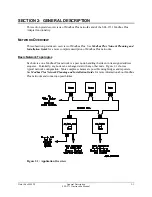
Страница 18: ...eration In Section 4 Operation Within SEL 2030 there is a description of the register addresses applicable to this data Figure 2 3 SEL 2711 Block Diagram Figure 2 3 shows a block diagram of the SEL 27...
Страница 19: ...Manual TABLE OF CONTENTS SECTION 3 OPERATION AND NETWORK CONFIGURATION 3 1 Introduction 3 1 Data Access 3 1 LED Usage 3 2 Self Tests 3 3 Device Configuration 3 3 Network Configuration 3 4 TABLES Table...
Страница 20: ......
Страница 21: ...rence the data using a Modbus offset value which starts at 0 this corresponds to how the holding register address is actually transmitted on the network so you must subtract 40001 from the 4x referenc...
Страница 22: ...etwork Planning and Installation Guide for more information on using redundant connections in a Modbus Plus network The green LED indicates network status The possible patterns are Six flashes per sec...
Страница 23: ...aps for meter demand meter target and history information If you select Y the holding register accesses will access the exact same data as the input register accesses See Section 4 Operation Within SE...
Страница 24: ...nections and are referred to as ports A and B See Modbus Plus Network Planning and Installation Guide for more information on using redundant connections in a Modbus Plus network In a typical non redu...
Страница 25: ...4 5 Configuring Relay Ports 4 5 Configuring SEL 2711 Port 4 12 Coil Data Mapping 4 16 Input Register Data Mapping 4 20 Holding Register Data Mapping 4 21 Relay Type 4 24 Meter Data 4 25 Demand Meter D...
Страница 26: ...ended Holding Register Map 4 23 Table 4 7 Relay Type Encodings 4 24 Table 4 8 Relay Meter Data Holding Register Map 4 25 Table 4 9 Relay Demand Meter Data Holding Register Map 4 26 Table 4 10 Date Tim...
Страница 27: ...board 5 Attach the snap on standoffs to the 80 position connector side of the SEL 2711 the standoffs are included in the materials shipped with the SEL 2711 Insert the SEL 2711 80 position connector...
Страница 28: ...a connected Protocol Card While in SELBOOT mode you can enter the HELP command to receive a description of the available commands 4 Use the BAU command to set the port baud rate as high as possible 3...
Страница 29: ...2030 you will need to change the baud rate on your communications software back to the value that is set in your SEL 2030 Front panel port settings This should be the same baud rate as was used in est...
Страница 30: ...that is reporting no self test failures Use the WHO command to confirm that the SEL 2711 is properly detected as Port 17 or 18 Use the STATUS command to confirm that no self test errors are reported...
Страница 31: ...ther Modbus Plus nodes on the same network should use a routing path such as 12 1 0 0 0 See Section 3 Operation and Network Configuration for more information on routing paths STATUS ACCESS The SEL 20...
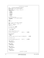
Страница 32: ...TIVE SEQUENCE BAUD 9600 DATABIT 8 STOPBIT 2 PARITY N RTS_CTS N XON_XOFF Y TIMEOUT OFF Save changes Y N Y ENTER Y ENTER Port 2 Settings Changed SET A 2 ENTER SET A 2 ENTER Automatic message settings fo...
Страница 33: ...HISTORY USER 0 Save changes Y N Y ENTER Y ENTER Port 2 Settings Changed SEL 2030 User Region data can also be read using the SEL 2711 Use SET M on the appropriate port to configure this data Port remo...
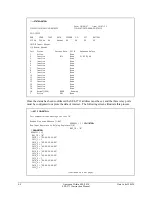
Страница 34: ...13 Inactive None 14 Inactive None 15 Inactive None 16 Inactive None 18 Normal 100h NORM Running F Active 98 None Once the status has been confirmed the SEL 2711 address must be set and the three rela...
Страница 35: ...ENTER Settings accepted SET P 1 ENTER SET P 1 ENTER Port communications settings for Port 1 Device Type U Unused S SEL IED O Other IED P Printer M Master DEVICE M S ENTER S ENTER Auto configure port Y...
Страница 36: ...d on Logic bit transition Y N SEND_OPER N Y ENTER ENTER Auto message Settings How many auto message sequences 0 12 MSG_CNT 0 4 ENTER 4 ENTER Item 1 trigger D1 ISSUE1 NA P00 00 01 ENTER P00 00 01 ENTER...
Страница 37: ...ogic settings for Port 1 SBR1 NA SRB1 ENTER SRB1 ENTER CBR1 NA CRB1 ENTER CRB1 ENTER SBR2 NA END ENTER END ENTER SBR1 1 SRB1 CBR1 1 CRB1 Save changes Y N Y ENTER Y ENTER Port 1 Settings Changed COPY 1...
Страница 38: ...lay ports are set up to collect data we can extract this data using Modbus Plus Simply connect a Modbus Plus master to the SEL 2711 and begin collecting data using the data maps provided later in this...
Страница 39: ...global data and control The first step is to create SET M equations on Port 18 for the global data we wish to transmit For this example we will send the phase currents and voltages from the three rela...
Страница 40: ...ion D1 Simply VIEW this data to see what is coming from the other nodes VIE 18 2060H NR 32 ENTER VIE 18 2060H NR 32 ENTER 18 2060h 000Ch 0000h FFFFh FFFFh FFFFh FFFFh 0000h 0000h 0000h 0000h 0000h 000...
Страница 41: ...H_2 00 00 00 00 00 END ENTER END ENTER ADDRESS 12 MAP_IR N PATH_1 2 5 0 COIL_1 36 PATH_2 00 00 00 00 00 COIL_2 1 PATH_3 00 00 00 00 00 COIL_3 1 PATH_4 00 00 00 00 00 COIL_4 1 PATH_5 00 00 00 00 00 COI...
Страница 42: ...30 A Modbus Force Single Coil ON message causes the corresponding SRB bit to be pulsed A Modbus Force Single Coil OFF message causes the corresponding CRB bit to be pulsed These bits can be used withi...
Страница 43: ...B3 47 3 RB2 48 3 RB1 49 4 RB16 50 4 RB15 51 4 RB14 52 4 RB13 53 4 RB12 54 4 RB11 55 4 RB10 56 4 RB9 57 4 RB8 58 4 RB7 59 4 RB6 60 4 RB5 Coil Number SEL 2030 Control Bit 61 4 RB4 62 4 RB3 63 4 RB2 64 4...
Страница 44: ...138 9 RB7 139 9 RB6 140 9 RB5 141 9 RB4 142 9 RB3 143 9 RB2 144 9 RB1 145 10 RB16 146 10 RB15 147 10 RB14 148 10 RB13 Coil Number SEL 2030 Control Bit 149 10 RB12 150 10 RB11 151 10 RB10 152 10 RB9 1...
Страница 45: ...25 15 RB16 226 15 RB15 227 15 RB14 228 15 RB13 229 15 RB12 230 15 RB11 231 15 RB10 232 15 RB9 233 15 RB8 234 15 RB7 235 15 RB6 236 15 RB5 Coil Number SEL 2030 Control Bit 237 15 RB4 238 15 RB3 239 15...
Страница 46: ...indicate the status of the last issued operation These will normally correspond to the values of the BRx bits within the SEL 2030 The following table lists the coil numbers for these bits Table 4 2 R...
Страница 47: ...egister offset address of a specific User Region register add the User Region offset address to the beginning input register for that port For example if you want to access register F932h on Port 13 f...
Страница 48: ...ta 5000 5499 Port 10 Relay Data 5500 5999 Port 11 Relay Data 6000 6499 Port 12 Relay Data 6500 6999 Port 13 Relay Data 7000 7499 Port 14 Relay Data 7500 7999 Port 15 Relay Data 8000 8499 Port 16 Relay...
Страница 49: ...history data from relay for this to be available see Table 4 13 for details Beyond the first 10000 registers exist registers that map to all the User Region data These registers function the same as t...
Страница 50: ...321 7 SEL BFR 2BFR 8 SEL 279H 9 SEL 151D 1 251D 1 10 SEL 151CD 1 251CD 1 1000 SEL PG10 2PG10 1001 SEL PG10 7 2PG10 7 1002 SEL PG10 8 2PG10 8 1010 SEL BFR 1 2BFR 1 1020 SEL 121 10 1021 SEL 121 16 221...
Страница 51: ...le 4 8 Relay Meter Data Holding Register Map Relative Address Description 40 IA IAX IAW1 or IA1 in amps or dVA or dV12 in secondary V 100 41 IB IBX IBW1 or IB1 in amps or dVB or dV34 in secondary V 10...
Страница 52: ...ess Description 60 Demand IA IAX or IAW1 in amps 61 Demand IB IBX or IBW1 in amps 62 Demand IC ICX or ICW1 in amps 63 Demand IR IRX or IRW1 in amps 64 Whole part of demand P in MW or demand IAY or IAW...
Страница 53: ...data acquisition 1 31 82 Year of last meter data acquisition 1900 2100 83 Hour of last meter data acquisition 84 Minute of last meter data acquisition 85 Second of last meter data acquisition Relay Wo...
Страница 54: ...vent Data Holding Register Map Relative Address Description 210 Month of last event 211 Day of last event 212 Year of last event 213 Hour of last event 214 Minute of last event 215 Second of last even...
Страница 55: ...4 14 for detailed breakdown 280 299 History Record 2 data see Table 4 14 for detailed breakdown 300 319 History Record 3 data see Table 4 14 for detailed breakdown 320 339 History Record 4 data see Ta...
Страница 56: ...ion below 8 Distance location whole part 9 Distance location fractional part multiplied by 10000 10 Shot 11 52 A in cycles 100 12 Group 13 Target see Target Type subsection below 14 Duration whole par...
Страница 57: ...CAT 7109 CG 7010 CGT 7110 1AB 1003 1ABC 1001 1ABCT 1101 1ABG 1002 1ABGT 1102 Event Code 1ABT 1103 1AG 1004 1AGT 1104 1BC 1006 1BCG 1005 1BCGT 1105 1BCT 1106 1BG 1007 1BGT 1107 1CA 1009 1CAG 1008 1CAGT...
Страница 58: ...Code 4CAT 4109 4CG 4010 4CGT 4110 52A1 46 52A2 47 52BT1 48 52BT2 49 59B 32 59L 33 5AB 5003 5ABC 5001 5ABCT 5101 5ABG 5002 5ABGT 5102 5ABT 5103 5AG 5004 5AGT 5104 5BC 5006 5BCG 5005 5BCGT 5105 5BCT 51...
Страница 59: ...8 EXT X 9029 EXT Y 9030 EXTC 17 FAULT 75 FAULT X 9003 FAULT Y 9004 G 62 H 63 HAB 6003 HABC 6001 HABCT 6101 HABG 6002 HABGT 6102 HABT 6103 HAG 6004 HAGT 6104 HBC 6006 HBCG 6005 HBCGT 6105 HBCT 6106 HBG...
Страница 60: ...Y 68 ZT 69 other 9999 Target Type Certain relays record the front panel target status at the time of each event Relays of this type save the event target information as a separate field of every even...
Страница 61: ...mary 32767 32767 MVAR 47 Reactive power fractional part Q MVAR 10000 primary 0 9999 0 9999 MVAR 48 Negative sequence current 3I2 amps primary 0 32767 A 49 Phase A voltage VA kV 10 primary 0 0 3276 7 k...
Страница 62: ...event months 1 12 211 Day of month of most recent event days 1 31 212 Year of most recent event years 1900 2100 213 Hour of most recent event hours 0 23 214 Minute of most recent event minutes 0 59 2...
Страница 63: ...ast meter data acquisition minutes 0 59 85 Second of last meter data acquisition seconds 0 59 86 159 Reserved always 8000h 160 Relay word rows 0 and 1 161 Relay word rows 2 and 3 162 Relay word rows 4...
Страница 64: ...IC amps primary 0 32767 A 63 Residual demand current IR amps primary 0 32767 A 64 Power demand whole part P MW primary 32767 32767 MW 65 Power demand fractional part P MW 10000 primary 0 9999 0 9999 M...
Страница 65: ...kV 55 CA differential voltage VCA kV 10 primary 0 0 3276 7 kV 56 Negative sequence voltage 3V2 kV 10 primary 0 0 3276 7 kV 57 AB difference current IAB amps primary 0 32767 A 58 BC difference current...
Страница 66: ...78 279 Unused always 8000h 280 2nd event month months 1 12 497 12th event fault current fractional part always 0 amps primary 0 498 499 Unused always 8000h SEL 501 SEL 501 using binary Fast Meter data...
Страница 67: ...211 Day of month of most recent event days 1 31 212 Year of most recent event years 1900 2100 213 Hour of most recent event hours 0 23 214 Minute of most recent event minutes 0 59 215 Second of most...
Страница 68: ...Reserved always 8000h 160 Relay word rows 0 and 1 161 Relay word rows 2 and 3 162 Relay word rows 4 and 5 163 Relay word rows 6 and 7 164 209 Reserved always 8000h 210 Month of most recent event mont...
Страница 69: ...data received from other nodes on the network in the D1 Region of the local port Port 17 or 18 database This data can then be used within the SEL 2030 by SET M Equations or by SELOGIC Control Equatio...
Страница 70: ...32 Database Address Corresponding Network Node 2400h 33 2420h 34 2440h 35 2460h 36 2480h 37 24A0h 38 24C0h 39 24E0h 40 2500h 41 2520h 42 2540h 43 2560h 44 2580h 45 25A0h 46 25C0h 47 25E0h 48 2600h 49...
Страница 71: ...ter reference Add 400 000 to obtain a 4x holding register reference Holding Register Map if MAP_IR N Holding Register Offset Address Description Holding Register Offset Address Description 1 499 Unuse...
Страница 72: ...tion Duration Flt Curr Flt Curr IV Time Energy 42015 Month Day Year Hour Minute Second Msec Event Type Flt Loc Flt Loc 43015 Shot 52A Group Targets Duration Duration Flt Curr Flt Curr IV Time Energy 4...
Страница 73: ...LE OF CONTENTS APPENDIX A FIRMWARE VERSIONS A 1 APPENDIX B ERROR CODES AND MESSAGES B 1 Self Test Failure Codes B 1 Error Messages B 2 APPENDIX C MODBUS PLUS MESSAGE EXAMPLE C 1 TABLES Table B 1 SEL 2...
Страница 74: ......
Страница 75: ...outgoing control and global data Requires SLBT 2711 R101 or later release of boot firmware Requires SEL 2030 R103 or later release of SEL 2030 firmware to enable all new features SLBT 2711 R101 Suppo...
Страница 76: ......
Страница 77: ...lash Failed Bit 3 Modbus Plus Dual Port RAM 0 Dual Port RAM OK 1 Dual Port RAM Failed Bit 4 Modbus Plus Peer Processor 0 Peer Processor OK 1 Internal Failure in Processor Bit 5 Cause of Peer Processor...
Страница 78: ...peer processor internal problem is the cause of the failure and the code n is listed in table B 2 MB Fail A general failure of the network processor has occurred Bit 4 and or 5 of error code will be s...
Страница 79: ...rror 0Ah global data address error 0Bh global data not present Table B 2 Peer Processor Internal Failures Hexadecimal Code Description 81h prom checksum error 82h int ram data test error 83h ext ram d...
Страница 80: ...Instruction Manual Hexadecimal Code Description 91h reserved rcv buf error 92h bad trans control state 93h bad work request bit 94h node queue overflow 95h bad data queue error 96h empty data path er...
Страница 81: ...lding register 02h starting address 539 40540 starting address less the 40001 base for holding registers 1Bh 00h register count 20 registers 40540 to 40559 inclusive 14h There are two response message...
Страница 82: ......
Страница 83: ...ter reference Add 400 000 to obtain a 4x holding register reference Holding Register Map if MAP_IR N Holding Register Offset Address Description Holding Register Offset Address Description 1 499 Unuse...
Страница 84: ...tion Duration Flt Curr Flt Curr IV Time Energy 42015 Month Day Year Hour Minute Second Msec Event Type Flt Loc Flt Loc 43015 Shot 52A Group Targets Duration Duration Flt Curr Flt Curr IV Time Energy 4...