


4-20
Operation Within SEL-2030
Date Code 980420
SEL-2711 Instruction Manual
Coil Number
SEL-2030
Control Bit
281
18:RB8
282
18:RB7
283
18:RB6
Coil Number
SEL-2030
Control Bit
284
18:RB5
285
18:RB4
286
18:RB3
287
18:RB2
288
18:RB1
The coil numbers passed within the Modbus messages are actually one less than those shown in the
above table.
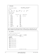
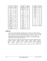
There is also a set of 16 coils corresponding to the 16 control commands the SEL-2711 can issue.
These are based on the 16 breaker bits (BRx bits) on the port in which the SEL-2711 card is
installed (17 or 18). These coils can only be read, not operated. They indicate the status of the last
issued operation. These will normally correspond to the values of the BRx bits within the
SEL-2030. The following table lists the coil numbers for these bits.
Table 4.2: Read-Only Coil Map
Coil Number
SEL-2030 Bit
289
BR16
290
BR15
291
BR14
292
BR13
293
BR12
294
BR11
295
BR10
296
BR9
297
BR8
298
BR7
299
BR6
300
BR5
301
BR4
302
BR3
303
BR2
304
BR1
I
NPUT
R
EGISTER
D
ATA
M
APPING
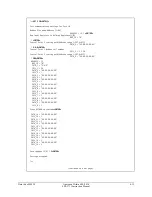
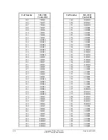
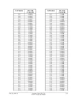
All of the User Region data within the SEL-2030 is available as input registers. The following
map lists the correspondence between the User Regions and the Input Register addresses. In this
table, offset addresses are used. To determine a 3x reference from this table, add 30000 to the
given offset address. Be aware that only the first 9999 registers will be available using 3x
references.