background image

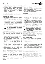
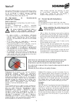
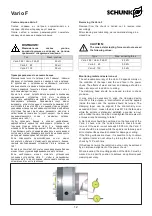
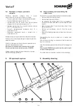
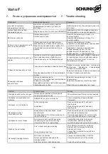
Vario F


Ø

144,

5


Ø

11

4,

5


Ø9

9

,5


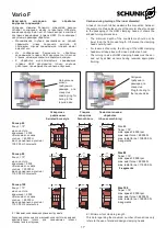
Действуйте 

осторожно 

при 

обработке 

внутреннего диаметра!


Удаление  слишком  большого  количества  резины 

ослабит  соединение  между  сегментами.  Обратите 

внимание на круглый лист, который входит в комплект 

поставки  зажимающих  головок  HSW.  Он  показывает 

допустимые размеры обработки.


• 

Минимальная  глубина  раззенковки  не  должна 

превышать  длину  переднего  выступа.  В 

противном  случае  зажимающая  головка  может 

вывалиться.


• 

Из 

соображений 

безопасности, 

обработка 

зажимающих головок HSW допускается только на 

станках, имеющих закрытые защитные кожухи.


• 

К  обработке  многосегментных  зажимающих 

головок  HSW  допускаются  только  опытные 

работники, прошедшие специальное обучение.


Caution during turning of the inner diameter!


A loss of too much rubber weakens the connection between 
the segments. Please take note of the circular sheet enclosed 
in  the  packaging  of  the  HSW  clamping  heads.  It  shows  the 
allowed turning dimensions.


• 

The  minimum  depth  of  the  counterbore  should  not  be 
lower than the front nose length. Otherwise the clamping 
head could tip over.


• 

For reasons of security, the turning of the HSW clamping 
heads must take place with closed protection hood.


• 

The turning to size of HSW clamping heads must be car- 
ried  out  by  skilled  workers  having  received  appropriate 
training.


Нагрузочное 

кольцо 

требуемого 

размера  для 

отверстия


Loading ring for 
boring to the 
required size


Заглушка


требуемого


размера


для


отверстия


Plug for boring to 
the required size


Отверстие


с


рифлением


Serrated bore style


Гладкое 

отверстие 

Smooth bore


Самостоятельная 

обработка 


Inhouse machining


Размер 65


Конус = 15°


макс. частота 

вращения = 6000 

об/мин макс. осевое 

усилие  = 45 000 Н


макс. радиальное усилие = 

105 000 Н 3 сегмента


58


SK 65 BZI


9


53


SK 65 BZIG


        4


53


SK 65 HSW


4


Size 65 
Taper = 15° 
max. speed = 6000 rpm 
max. axial force = 45 000 N 
max. radial force = 105 000 N 
3-segments


E = 11 мм


E = 6 

мм


E = 6 

мм


Размер 80


Конус = 15°


макс. частота 

вращения = 5500 

об/мин макс. осевое 

усилие  = 50 000 Н


макс. радиальное усилие = 

115 000 Н 3 сегмента


53  


        4


SK 80 BZI


53  


        4


SK 80 BZIG


53  


        4


SK 80 HSW


Size 80 

Taper = 15° 
max. speed = 5500 rpm 
max. axial force = 50 000N 
max. radial force = 115 000 N 

3-segments 

E = 6 мм


E = 6 мм


E = 6 мм


Размер 100


Конус = 15°


макс. частота 

вращения = 5000 

об/мин макс. осевое 

усилие  = 65 000 Н


макс. радиальное усилие = 

115 000 Н 6 сегментов


      59  


SK 100 BZ


      59  


SK 100 BZG


      59  


SK 100 HSW


Size 100 

Taper = 15° 
max. speed = 5000 rpm 
max. axial force = 65 000 N 
max. radial force = 150 000 N 
6-segments

E = 2 

мм


E = 2 мм


E = 2 мм


E = Минимальная зажимная длина инструмента


Значения, указанные для максимальной частоты вращения, 

действительны  только  для  зажимающих  головок 

стандартной конструкции.


E = Minimum tool clamping length


This data regarding the maximum number of revolutions only 
refers to the use of standard design clamping heads.


17


Содержание Vario F 100

Страница 1: ...1 905 712 2210 info ca schunk com www ca schunk com SCHUNKPrecisionMachinery 86 571 8672 1000 86 571 8673 8800 info cn schunk com www cn schunk com SCHUNKIntecs r o 420 545229095 420 545220508 info c...

Страница 2: ...c Safety Notes 9 3 Scope of Delivery 9 4 Product Description 10 5 Assembly 11 5 1 Mounting the segmented mandrel on the power chuck 11 5 2 Changing the segmented clamping sleeve 11 5 3 Changing the En...

Страница 3: ...to observe the current safety regulations and legal prerequisites to avoid damage to persons and to the product during maintenance and repair work Before carrying out repairs personnel must have read...

Страница 4: ...being in charge with tasks of the collet chuck must have read the relevant documentation before setting to work and in particular being familiar himself with the chapter dealing with Safety This is pa...

Страница 5: ...ned according to the respective standards that apply and or the most up to date scientific and technological data e g VDI 3106 Principles The collet chuck complies with the specific safety regulations...

Страница 6: ...tective windows because this may cause a threat to the life and limb of the operator in the case of a fracture in the chuck jaws Please observe all appropriate safety measures during the transportatio...

Страница 7: ...y be carried out by reliable personnel the legal minimum age must be obser ved Only employ personnel on the collet chuck which has been trained and shown how to operate the mandrel Make use of the man...

Страница 8: ...g device the machine must be equipped with a speed limiting device If the clamping device is changed it is important to adjust the stroke control to suit the new situation The centrifugal force of the...

Страница 9: ...of the machi ne can cause injury Do not use solvents containing ester or polar solvents for cleaning the Vario F Seals and segmented clamping slee ves could otherwise be damaged The collet chuck is b...

Страница 10: ...addition the entire clamping device is stiffened this has a positive effect on the service life of the tools The Vario F is a collet chuck which must be integrated into a ROTA THW vario 215 62 only Th...

Страница 11: ...om the chuck and insert protective jaws Item 82 up to the max position marking on the chuck face The chuck mechanism is opened when chan ging the center sleeve or the Vario component When doing this e...

Страница 12: ...dial indicator should be applied inside the taper and the spindle should be turned The clamping taper can be aligned if the concentricity error exceeds 0 01 mm Loosen the 6 screws M 10 in the face sid...

Страница 13: ...hand Removing the SPANNTOP Clamping Head The removing of the Clamping Head is only possible when the chuck is in the changing position front position Attach the Changing Fixture see the separate parag...

Страница 14: ...nd chuck body Item 1 from the mount Item 2 Remove pull mechanism Item 3 from the mount Item 2 Expand the fastening taper and pull down over the mount Item 2 Disassembling the chuck is carried out in r...

Страница 15: ...ove drawtube back and clean slot in coupling area Check drawtube adapter 10 or draw mecha nism 4 position and adjust it if necessary Workpiece bent out of shape A work piece is bent out of shape durin...

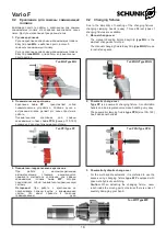
Страница 16: ...ews 3 11 Fastening screws 6 12 Fastening screws 6 13 Seal 1 14 Seal 1 9 9 1 HSW Vario F HSW HSW Vario F 0 3 9 Accessories 9 1 HSW clamping heads for in house machining to the required size For precisi...

Страница 17: ...g Loading ring for boring to the required size Plug for boring to the required size Serrated bore style Smooth bore Inhouse machining 65 15 6000 45 000 105 000 3 58 SK 65 BZI 9 53 SK 65 BZIG 4 53 SK 6...

Страница 18: ...QQ Type MQQ 2 PP PPG 100 160 2 2 Pneumatic change over Type PP is a pneumatic changing fixture A comfortable handle and an integrated valve make handling very easy The pneumatic clamping fixture type...

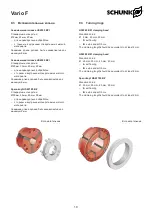
Страница 19: ...ng length should be equivalent to at least 6 mm HSW 80 BZI clamping head Standard bores 20 mm 30 mm 40 mm 60 mm for self boring face side and soft bore The clamping length should be equivalent to at l...

Страница 20: ......

Отзывы: