background image

Vario F


5.2 

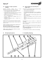
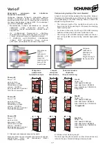
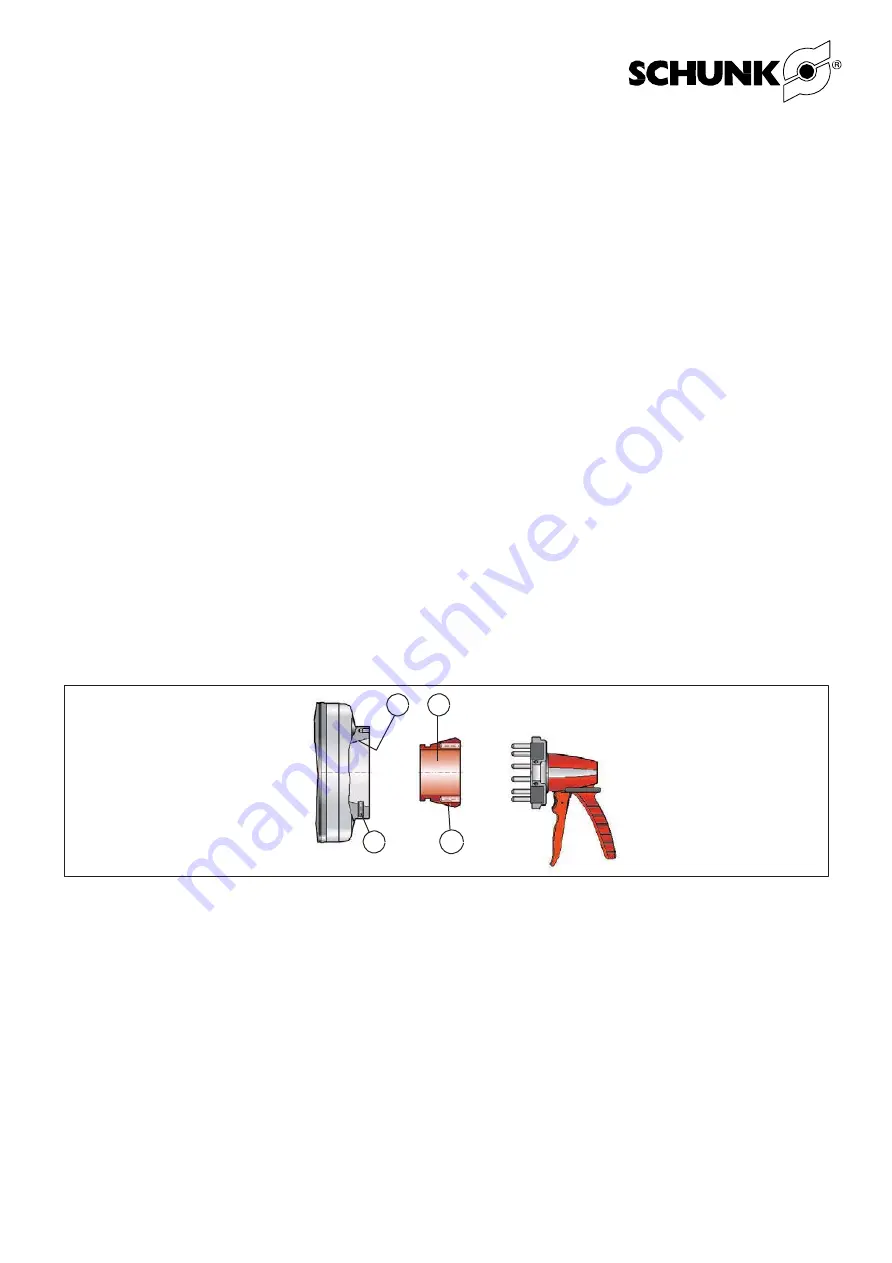
Установка  зажимающей  головки 

Vario F


Замена зажимающей головки возможна только при условии, 

что  штатный  патрон  станка  находится  в  положении  для 

замены 

(переднее 

положение). 

Перед 

заменой 

зажимающей головки (1) очистите конус на корпусе патрона 

(2).  Установите  на  зажимающую  головку  крепление  для 

замены  (см.  раздел  «Крепления  для  замены  зажимающих 

головок»).  Вставьте  штифты  крепления  до  упора  в 

соответствующие отверстия на торце зажимающей головки. 

Срабатывая, крепление оказывает усилие на зажимающую 

головку  (1),  в  результате  чего  сегменты  в  области 

крепления  сходятся  друг  с  другом.  Установите 

зажимающую  головку  внутрь  корпуса  патрона.  При  этом 

установочный винт (6) войдет в зацепление с канавками (7), 

вырезанными  в  центрах  сегментов  (никогда  не  помещайте 

их внутрь вулканизированных пазов).


Слегка  прижмите  крепление  для  замены  зажимающих 

головок к шпинделю, чтобы ослабить зажимающую головку, 

а затем снимите его.


ОСТОРОЖНО: 

При работе с креплением не просовывайте 

пальцы  внутрь,  к  вращающимся  частям.  Это  может 

привести к раздавливанию руки.


Снятие зажимающей головки SPANNTOP


Снятие зажимающей головки возможно только при условии, 

что  патрон  находится  в  положении  для  замены  (переднее 

положение).  Установите  крепление


для  замены  (см. 

отдельный  пункт  с  описанием  этого  устройства)  на 

зажимающую  головку.  Вставьте  штифты  крепления  до 

упора в соответствующие отверстия на торце зажимающей 

головки.  Срабатывая,  крепление  оказывает  усилие  на 

зажимающую  головку  (1),  в  результате


чего  сегменты  в 

области  крепления  сходятся  друг  с  другом.  Снимите 

крепление


вместе  с  зажимающей  головкой  с  патрона, 

ослабьте крепление


и снимите с него зажимающую головку.


5.2  Inserting the Vario F clamping head


Changing  of  the  clamping  head  is  only  possible  when  the 
power chuck is in changing position (front position). Clean the 
taper  in  the  chuck  body  (2)  before  changing  the  clamping 
head  (1).  Attach the changing  fixture  (chapter  on  »changing 
fixtures«)  to  the  clamping  head.  Insert  the  pins  of  the 
changing  fixture  fully  into  the  matching  holes  on  the  face  of 
the  clamping  head.  Actuating  the  changing  fixture  will  force 
the  clamping  head  (1)  segments  in  the  coupling  area 
together.  Place  the  clamping  head  inside  the  chuck  body. 
This will engage the locating screw (6) with the milled setting 
grooves  (17)  of  the  segment  centers  (never  place  them 
inside the vulcanized slots).


Apply  slight  pressure  on  the  changing  fixture  towards  the 
spindle to loosen the clamping head and then remove it.


CAUTION: 

When actuating the changing fixture, never reach 

inside the moving parts, otherwise there is a risk of crushing 
your hand.


Removing the SPANNTOP Clamping Head


The removing of the Clamping Head is only possible when the 
chuck  is  in  the  changing  position  (front  position).  Attach  the 
Changing Fixture (see the separate paragraphe covering the 
Changing  Fixture)  to  the  Clamping  Head.  Insert  the  pins  of 
the Changing Fixture fully into the matching hols on the face 
of  the  Clamping  Head.  Actuating  the  Changing  Fixture 
will force the Ckampoing Head (1) segments in the coupling 
area together. Take the Changing Fixture, with the Clamping 
Head attached,  out  of  the  chuck,  loosen  the  Changing 
Fixture and remove the Clamping Head.


1


17


5.3 

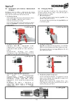
Задние упоры


В качестве осевого заднего упора для цангового патрона 

используется шайба.


В  эту  шайбу  может  быть  установлена  специальная 

проставка. M12 для F 65 и Vario F 80, M20 x 1.5 для Vario


F100. Кроме того, можно отвинтить шайбу и подвергнуть 

ее  механической  обработке.  При  этом  необходимо 

соблюдать осторожность, так как в результате обработки


на  шайбе  не  должно  образоваться  отверстий, 

открывающих  внутреннюю  часть  цангового  патрона. 

Через  такие  отверстия  в  патрон  может  попадать  грязь, 

что негативно скажется на его работе.


Если  осевой  задний  упор  не  требуется,  отверстие  для 

него необходимо заглушить стопорным винтом.


5.3  Back stops


A  washer  is  installed  for  the  axial  back  stop  in  the  collet 
chuck.


A specific intermediate piece can be installed in this washer. 
M12 for Vario F 65 and Vario F 80 and M20 x 1.5 for Vario F


100. The washer can also be unscrewed and reworked. When 
reworking,  it  must  be  ensured  that  no  openings  are  created 
which might expose the interior. The collet style chuck may be 
soiled through the openings which will impede operations.


If  no  axial  back  stop  is  required,  the  bore  should  be  sealed 
with a locking screw.


13


Содержание Vario F 100

Страница 1: ...1 905 712 2210 info ca schunk com www ca schunk com SCHUNKPrecisionMachinery 86 571 8672 1000 86 571 8673 8800 info cn schunk com www cn schunk com SCHUNKIntecs r o 420 545229095 420 545220508 info c...

Страница 2: ...c Safety Notes 9 3 Scope of Delivery 9 4 Product Description 10 5 Assembly 11 5 1 Mounting the segmented mandrel on the power chuck 11 5 2 Changing the segmented clamping sleeve 11 5 3 Changing the En...

Страница 3: ...to observe the current safety regulations and legal prerequisites to avoid damage to persons and to the product during maintenance and repair work Before carrying out repairs personnel must have read...

Страница 4: ...being in charge with tasks of the collet chuck must have read the relevant documentation before setting to work and in particular being familiar himself with the chapter dealing with Safety This is pa...

Страница 5: ...ned according to the respective standards that apply and or the most up to date scientific and technological data e g VDI 3106 Principles The collet chuck complies with the specific safety regulations...

Страница 6: ...tective windows because this may cause a threat to the life and limb of the operator in the case of a fracture in the chuck jaws Please observe all appropriate safety measures during the transportatio...

Страница 7: ...y be carried out by reliable personnel the legal minimum age must be obser ved Only employ personnel on the collet chuck which has been trained and shown how to operate the mandrel Make use of the man...

Страница 8: ...g device the machine must be equipped with a speed limiting device If the clamping device is changed it is important to adjust the stroke control to suit the new situation The centrifugal force of the...

Страница 9: ...of the machi ne can cause injury Do not use solvents containing ester or polar solvents for cleaning the Vario F Seals and segmented clamping slee ves could otherwise be damaged The collet chuck is b...

Страница 10: ...addition the entire clamping device is stiffened this has a positive effect on the service life of the tools The Vario F is a collet chuck which must be integrated into a ROTA THW vario 215 62 only Th...

Страница 11: ...om the chuck and insert protective jaws Item 82 up to the max position marking on the chuck face The chuck mechanism is opened when chan ging the center sleeve or the Vario component When doing this e...

Страница 12: ...dial indicator should be applied inside the taper and the spindle should be turned The clamping taper can be aligned if the concentricity error exceeds 0 01 mm Loosen the 6 screws M 10 in the face sid...

Страница 13: ...hand Removing the SPANNTOP Clamping Head The removing of the Clamping Head is only possible when the chuck is in the changing position front position Attach the Changing Fixture see the separate parag...

Страница 14: ...nd chuck body Item 1 from the mount Item 2 Remove pull mechanism Item 3 from the mount Item 2 Expand the fastening taper and pull down over the mount Item 2 Disassembling the chuck is carried out in r...

Страница 15: ...ove drawtube back and clean slot in coupling area Check drawtube adapter 10 or draw mecha nism 4 position and adjust it if necessary Workpiece bent out of shape A work piece is bent out of shape durin...

Страница 16: ...ews 3 11 Fastening screws 6 12 Fastening screws 6 13 Seal 1 14 Seal 1 9 9 1 HSW Vario F HSW HSW Vario F 0 3 9 Accessories 9 1 HSW clamping heads for in house machining to the required size For precisi...

Страница 17: ...g Loading ring for boring to the required size Plug for boring to the required size Serrated bore style Smooth bore Inhouse machining 65 15 6000 45 000 105 000 3 58 SK 65 BZI 9 53 SK 65 BZIG 4 53 SK 6...

Страница 18: ...QQ Type MQQ 2 PP PPG 100 160 2 2 Pneumatic change over Type PP is a pneumatic changing fixture A comfortable handle and an integrated valve make handling very easy The pneumatic clamping fixture type...

Страница 19: ...ng length should be equivalent to at least 6 mm HSW 80 BZI clamping head Standard bores 20 mm 30 mm 40 mm 60 mm for self boring face side and soft bore The clamping length should be equivalent to at l...

Страница 20: ......
Отзывы: