


Assembly and settings
14
03.00 | Clamping Device SVP-2 | Assembly and Operting Manual | en | 0289021
Ø
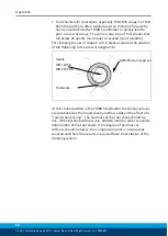
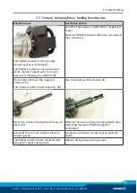
Carefully draw the movable side (6) of the caliper gauge (1)
away. Then guide the caliper gauge from left to right through
the two slotted bearings (7) of the bracket of the base body (8)
of the clamping device. Push the movable side (6) again onto
the caliper gauge and secure it with the safety pin (5) in the
bore on the rear of the caliper gauge.
Ø
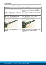
In order to reach the cutter of your tool (9), you will need an
extension of the caliper gauge side. Turn the knurled screw (4)
into the bracket (3). Push one bracket over each side of the
caliper gauge (1) and insert the measuring legs (2) into the
bracket with the slotted side facing the caliper gauge side (see
illustration)
Ø
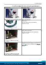
After having inserted the measuring legs (2) into the required
position, fix the bracket (3) with the knurled screw (4).
Ø
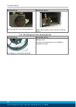
To determine the zero point of the caliper gauge, swivel up the
two measuring arms and slide towards one another. Set the
caliper gauge´s display to zero (see illustration).


