33
Montage- und Betriebsanleitung für
2-Finger-Parallelgreifer Type PGN-plus
Assembly and Operating Manual for
2-Finger Parallel Gripper Type PGN-plus
Montage und Einstellung der induktiven
Näherungsschalter (INW 80/S)
Technische Daten:
Spannung:
10 – 30 V DC
Restwelligkeit:
≤
15%
Schaltstrom max.:
200 mA, kurzschlussfest
Schalthysterese:
≤
15% vom Nennschaltabstand
Temperaturbereich:
– 25°C bis + 70°C
Schaltfrequenz max.:
1000 Hz
Spannungsabfall ca.:
1.5 V
Schutzart nach DIN 40050:
IP 67*
* für die Rundsteckverbindung nur im verschraubten Zustand
Assembly and adjustment of the inductive
proximity-switches (INS 80/S)
Technical data:
Supply voltage:
10 – 30 V DC
Operation voltage:
≤
15%
Max load current:
200 mA, short circuit proof
Hysteresis:
≤
15% of nominal sensing distance
Range of operat. temp.:
– 25°C ... + 70°C
Max operating frequency:
1000 Hz
Voltage drop, approx.:
1.5 V
Protection class DIN 40050: IP 67*
* only when screwed in place in case of circular connector
Schaltfunktion: in unbedämpftem Zustand gezeichnet
Output: drawn in non-actuated condition
2 Stück / 2 pieces
Type
Schaltfunktion / Output
Ident-Nr. / Id.-No.
INW 80/S-M
Schließer / Closer
301 408
INW 80/S-M12
301 508
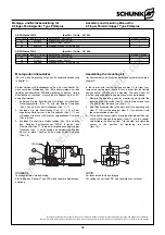
Montage des Anbausatzes
(Pos.-Nr. siehe Darstellung auf Seite 34)
ANMERKUNG:
Die Schaltpunkte der Stellung geöffnet und geschlossen wurden
vorab von der Firma SCHUNK eingestellt.
Bei der Version mit Staubabdeckung (Pos.-Nr. siehe Kapitel 9.2)
müssen vorab die Dichtbolzen (Pos. 85) entfernt werden, um die
Näherungsschalter montieren zu können. Um die Schaltnocken
verstellen zu können, müssen vorab die Gewindestifte (Pos. 49)
herausgedreht werden.
Greifer geöffnet:
1.
Schieben Sie den Näherungsschalter 1 auf Anschlag in den
Klemmhalter (Pos. 17) und befestigen Sie ihn durch
Anziehen der Schraube (Pos. 17a).
2.
Stellen Sie den Greifer in Stellung »Auf« und testen Sie die
Funktion.
Greifer geschlossen:
1.
Schieben Sie den Näherungsschalter 2 in den Klemmhalter
(Pos. 17) auf Anschlag und befestigen Sie ihn durch
Anziehen der Schraube (Pos. 17a).
2.
Stellen Sie den Greifer in Stellung »Zu« und testen Sie die
Funktion.
Teil gegriffen (Außengreifen)
1.
Schieben Sie den Näherungsschalter 2 auf Anschlag in den
Klemmhalter (Pos. 17) und befestigen Sie ihn durch
Anziehen der Schraube (Pos. 17a).
2.
Spannen Sie das zu greifende Teil.
3.
Lösen Sie die Schraube (Pos. 42). Bei der Version mit
Staubabdeckung müssen die Gewindestifte aus den
seitlichen Abdeckungen entfernt werden, um die Schrauben
(Pos. 42, 43) verstellen zu können.
Assembly of the attachment set
(for item numbers, see illustration on page 34)
REMARK:
The switching points for the open and closed positions were pre-
set by SCHUNK.
In the version with dust cover (see chapter 9.2 for item No.),
remove the sealing bolts (item 85) first, in order that the proximity
switch can be mounted. The set-screws (item 49) must be
unscrewed completely before the operating cams can be
adjusted.
Gripper open:
1.
Move proximity switch 1 to the stop in the bracket (item 17)
and fasten it by tightening the screw (item 17a).
2.
Move the gripper to the “open” position and perform a
function test.
Gripper closed:
1.
Move proximity switch 2 to the stop in the bracket (item 17)
and fasten it by tightening the screw (item 17a).
2.
Move the gripper to the “closed” position and perform a
function test.
Workpiece gripped (O.D. gripping)
1.
Move proximity switch 2 to the stop in the bracket (item 17)
and fasten it by tightening the screw (item 17a).
2.
Clamp the workpiece to be gripped.
3.
Undo the screw (item 42). Untighten the screw (item 42). In
case of versions with dust cover, the set-screws from the
lateral cover have to be removed so that the screws
(item 42, 43) can be adjusted.
Air-Oil Systems, Inc. www.airoil.com


