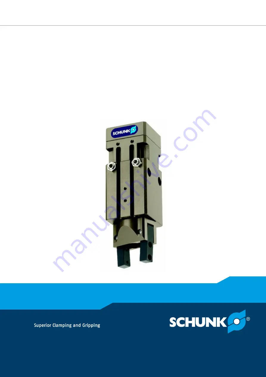
Original operating manual
Assembly and operating manualGSM-W
Rotary gripping module with angular gripper
Страница 1: ...Original operating manual Assembly and operating manual GSM W Rotary gripping module with angular gripper...
Страница 2: ...ations for the purpose of technical improvement Document number 389108 Version 03 00 12 04 2019 en SCHUNK GmbH Co KG All rights reserved Dear Customer thank you for trusting our products and our famil...
Страница 3: ...t intended use 8 2 3 Constructional changes 8 2 4 Spare parts 8 2 5 Gripper fingers 9 2 6 Environmental and operating conditions 9 2 7 Personnel qualification 9 2 8 Personal protective equipment 10 2...
Страница 4: ...is not executed immediately 36 8 Maintenance 37 8 1 Notes 37 8 2 Maintenance and care intervals 37 8 3 Grease greasing areas 38 8 4 Screw tightening torques 39 8 5 Disassembly assembly of the unit in...
Страница 5: ...s manual Illustrations in this manual are provided for basic understanding and may differ from the actual product design In addition to these instructions the documents listed under Applicable documen...
Страница 6: ...ntenance O D gripping AS 1 2 Warranty If the product is used as intended the warranty is valid for 24 months from the ex works delivery date under the following conditions Observe the specified mainte...
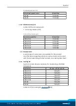
Страница 7: ...5 5514446 GSM W 32 5514447 GSM W 40 5514448 1 4 Accessories A wide range of accessories are available for this product For information regarding which accessory articles can be used with the correspon...
Страница 8: ...complied with The product is intended for industrial and industry oriented use Appropriate use of the product includes compliance with all instructions in this manual 2 2 Not intended use It is not i...
Страница 9: ...serious injuries considerable material damage and or a significant reduction to the product s life span Make sure that the product is a sufficient size for the application Ensure that maintenance and...
Страница 10: ...our Service personnel of the manufacturer Due to its technical training knowledge and experience service personnel of the manufacturer is able to perform the delegated tasks and to recognize and avoid...
Страница 11: ...vention and environ mental protection regulations regarding the product s applica tion field 2 10 Transport Handling during transport Incorrect handling during transport may impair the product s safet...
Страница 12: ...emains in the system If the energy supply is connected do not move any parts by hand Do not reach into the open mechanism or movement area of the product during operation 2 13 1 Protection during hand...
Страница 13: ...ue through technical safety measures The protective cover and protective fence must be rigid enough to withstand the maximum possible movement energy EMERGENCY STOP switches must be easily and quickly...
Страница 14: ...can lead to serious injury or death Take appropriate protective measures to secure the danger zone WARNING Risk of injury due to unexpected movements If the power supply is switched on or residual ene...
Страница 15: ...force maintenance Secure the end positions of the product with SCHUNK SDV P pressure maintenance valves WARNING Danger of injury due to uncontrolled movements Due to incorrect control and incorrect o...
Страница 16: ...sion dB A 70 IP rating 30 Pressure medium Compressed air compressed air quality according to ISO 8573 1 7 4 4 Nominal working pressure bar 6 Min pressure bar for gripping with gripping force maintenan...
Страница 17: ...89108 17 4 Design and description 4 1 Design Rotary gripping module with angular gripper 1 Compressed air main connection 2 DKM feed through compact module 3 Base jaws 4 WGM gripping module 5 Rotor dr...
Страница 18: ...t of inertia of the fingers is exceeded the gripper can be damaged A jaw movement always has to be without jerks and bounce You must therefore implement sufficient reduction and or damping Observe the...
Страница 19: ...ns OR Screw on throttle valve in order to be able to perform sufficient throttling and or dampening Screw the product to the machine system Mechanical connection 20 If necessary use appropriate connec...
Страница 20: ...ng adapter plates should be made of non ferromagnetic material Item GSM SFL basic size 40 64 1A 1B 1C Centering sleeve for lateral mounting of the unit and fitting depth in the mounting plate 8 2 5 de...
Страница 21: ...be used for the secure transmission of shearing forces and positioning of the unit Mounting the unit at the side with adapter plate similar to A B or C The assembly of the unit can be carried out fro...
Страница 22: ...e central air unit must be equipped with a maintenance unit that is located as near as possible to the consumer NOTICE If the end positions of the stroke and swivel movements are not impact free and b...
Страница 23: ...N position Hose free direct connection d If direct connections a d are used use the locking screws included in the accessory pack for the corresponding main connections A D If air connections a d are...
Страница 24: ...manual and catalog datasheet are included in the scope of delivery for the sensors and are available at schunk com Information on handling sensors is available at schunk com or from SCHUNK contact per...
Страница 25: ...int of the sensor of the right groove SGR1 or SGR2 is active The sequence of the swivel and closing movements process sequence defined during the teach process must also be followed during operation O...
Страница 26: ...justment range of end angle Switching range of sensor Rotating angle setting and monitoring range GSM 5 3 4 Settings for magnetic switch NOTE The installation dimensions shown only apply if the clampi...
Страница 27: ...stroke For grippers with X mm nominal stroke per jaw Min query range per jaw min queried stroke difference per jaw X 5 mm 30 of the nominal stroke per jaw X 5 mm to X 10 mm 20 of the nominal stroke p...
Страница 28: ...MMS P Determining the clamping position of the MMS P sensor Monitoring GSM locations positions end positions SGL1 left rotating angle end position gripper position 1 SGL2 left rotating angle end posi...
Страница 29: ...load information from our homepage Technical data for the sensors can be found in the data sheets included in the scope of delivery 5 4 Mounting a customized construction NOTICE Damage to the unit dur...
Страница 30: ...top but only up to the maximum projection dimension B For projection dimensions A and B see the following table Total rotation angle range When the rotating angle is set tighten the counter nut 124 Ac...
Страница 31: ...ion is described in the following chapters for S variants Replacing a shock absorber for S variants for E variants Replacing an elastomer for E variants NOTICE The permissible minimum and maximum proj...
Страница 32: ...e Adjustment range of end angle Switching range of sensor e n d a n g l e s t a r t a n g l e s t a r t a n g l e end angle Swivel range Adjustment range of start angle Adjustment range of end angle S...
Страница 33: ...ow control valves and shock absorbers must be used Setting the speed 33 and Adjustment of the shock absorber stroke 34 Please observe the information in the catalog pages 6 1 Setting the speed NOTICE...
Страница 34: ...smooth motion may also be too slow in many use cases Further settings can be made via the shock absorbers Adjustment of the shock absorber stroke 34 6 2 Adjustment of the shock absorber stroke NOTE Wh...
Страница 35: ...et position End position Target time Time T Damping Optimal shock absorber stroke 6 3 Restart after long standstill During a longer shutdown no compressed air may be applied to the gripper If issues o...
Страница 36: ...nes between the product and directional control valve as short as possible Flow rate of valve is sufficiently large relative to the compressed air consumption NOTICE The throttle check valve must not...
Страница 37: ...ith base jaws as a set NOTICE The needle rollers are suitable only for this product and cannot be replaced with needle rollers belonging to another product of the same type and size 8 2 Maintenance an...
Страница 38: ...15 Item 35 Item 85 Item 122 Mixture of Interflon Fin assembly grease for Interflon Fin Lupe EP mass ratio 1 1 Item 103 Item 11 Item 82 Item 42 Item 43 Item 44 Item 46 Item 51 Item 52 Item 53 Item 58...
Страница 39: ...Nm FAN 64 3 1 Nm 8 5 Disassembly assembly of the unit in the basic modules Position of the item numbers Drawings 49 Disassembly Remove the compressed air lines Turn the gripping module GSM into the mi...
Страница 40: ...gs 102 from the piston Loosen the screws 112 and remove the holders 8 Take the needle rollers 15 out of the cover housing and remove the needle rollers 13 and 14 Use the piston rod 4 to pull the finge...
Страница 41: ...of the magnets item 120 43 Carefully fit the cover housing 35 with the mounted parts into the bushing 44 Screw the cover housing 35 into the bushing 44 using the screws 111 8 6 2 Version with maintena...
Страница 42: ...f the gripping force make sure the spring 121 is inserted in the bushing 46 between steps 12 and 13 of assembly without maintenance of the grip ping force I D gripping version GSM IS Disassembly Repea...
Страница 43: ...ariants Top view in rotating angle position for 0 90 variants 8 7 Disassembly assembly of the DKM feed through compact module item 40 Position of the item numbers Drawings 49 NOTICE If the housing 11...
Страница 44: ...ows Remove the shock absorber 120 after loosening the nuts 121 Also remove the sleeves 122 Assembly For assembly observe the permissible tightening torques as well as the greases and adhesives to be u...
Страница 45: ...shock absorbers have a limited lifespan depending on the load For this reason their function should be checked regularly The shock absorber is working correctly if the unit moves gently to the end pos...
Страница 46: ...ered Proceed as follows with the replacement Remove the compressed air lines Loosen the counter nut 124 Remove the shock absorber 121 from the unit and remove the sleeve 122 If the latter cannot be lo...
Страница 47: ...position on the stop rotor 58 and grease the two parts completely again Put the stop rotor in the correct position in the intended fit in the upper rotor housing 51 Grease the entire rotor 53 except...
Страница 48: ...ricant Grease greasing areas 38 Oil or grease bare external steel parts Replace all wear parts seals Position of the wearing parts Drawings 49 Seal kit Sealing kit 7 Assembly Assembly takes place in t...
Страница 49: ...wing figures are example images They serve for illustration and assignment of the spare parts Variations are possible depending on size and variant 8 12 1 Assembly drawing of the basic module Basic mo...
Страница 50: ...W Assembly and operating manual en 389108 8 12 2 Assembly drawing for the DKM and FAN modules DKM and FAN overview Included in the seal kit Seal kit can only be ordered completely Only for the basic s...
Страница 51: ...e 03 00 GSM W Assembly and operating manual en 389108 51 8 12 3 Assembly drawing of the gripping modules Assembly drawing of the basic modules Included in the parts list for the DKM feed through compa...
Страница 52: ...957 0303876 0303976 0303877 0303977 0303886 0303986 0303887 0303987 0304616 0304617 0304636 0304736 0304637 0304737 0304646 0304746 0304647 0304747 0304656 0304756 0304657 0304757 0304676 0304776 0304...
Страница 53: ...37 0304646 0304746 0304647 0304747 0304656 0304756 0304657 0304757 0304676 0304776 0304677 0304777 0304686 0304786 0304687 0304787 To be provided by the System Integrator for the overall machine Fulfi...
Страница 54: ...ks of uncontrolled movements X 1 4 Required characteristics of guards and protective devices 1 4 1 General requirements X 1 4 2 Special requirements for guards X 1 4 2 1 Fixed guards X 1 4 2 2 Interlo...
Страница 55: ...on from Annex 1 is to be supplemented from here forward 2 Supplementary essential health and safety requirements for certain categories of machinery X 2 1 Foodstuffs machinery and machinery for cosmet...
Страница 56: ...56 03 00 GSM W Assembly and operating manual en 389108...