14 • Schlage • CT5000 user guide
Handheld Device (HHD)
The Handheld Device is used for programming and setup only.
The HHD is used to configure the CT5000. This includes transferring data files between the
access control software and the CT5000. Refer to the SUS user guide for more information
about the HHD.
To connect the HHD to the CT5000:
L
If a remote USB connection is being used, begin at step 3.
1. Loosen the 6 screws and remove the CT5000 lid. The POWER LED should blink green
when the lid is off.
2. Verify power is connected to the CT5000.
3. Log in to the SUS software. See the SUS User Guide at www.allegion.com/us (see
Support>Schlage Electronics>Electronic Locks Technical Library).
L
Make sure the HHD connection type is set to “USB Connection”.
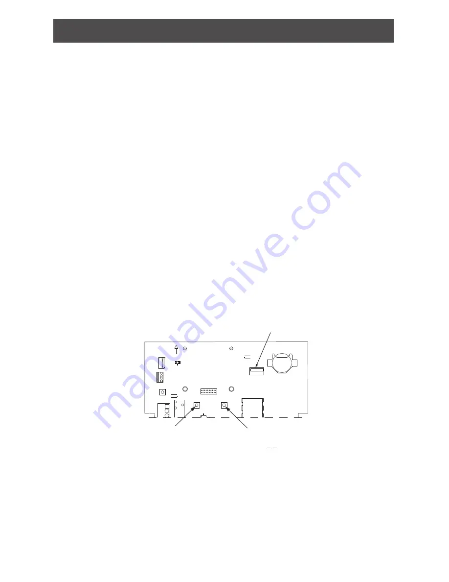
4. Connect the HHD to J5 USB port, or to the USB wall plate if a remote USB connection is
used. The CT5000’s USB LED will blink green.
The CT5000 is communicating with the HHD when the USB LED blinks green and the
HHD display indicates “new lock”, “no door data available” or the name of the door file.
The SUS is now ready to view the CT5000 settings.
5. To Edit Settings or Update Firmware on the CT5000, the SUS software and the CT5000
must be coupled.To couple the CT5000 and the HHD:
• On the CT5000, press and hold the SCHLAGE button while pressing the LINK
button three (3) times within 5 seconds.
• The USB LED will blink red and green. On the SUS, select the option “Couple HHD
to Device”. SUS will report when coupling is successful.
• Successful coupling will be indicated on the CT5000 with a blinking green USB LED.
+
-
+
-
C
B+
1
+
+
1
IF RADIO BOARD PRESENT
NC
COIN CELL NOT NEEDED
NC
C
NO
C
NO
PRIMARY SIDE
ALARM
STRIKE
AUX
SIDE UP
LINE
DEBUG
STATUS
RELAY
RX/TX
USB
+12V
+5V
+3.3V
RX
TX
GND
OPEN
A-
1
1
1
1
1
1
23394075_C
SCHLAGE
LINK
RESET
GND
20
19
2
1
ICLK
IDAT
RB8
RB7
GND
VDD
MCLR
USB
BATT
LINE
ALR_NC
ALR_C
ALR_NO
AUX
AUX
AUX
STR
STR
STR
12/24VDC
THIS
MOUNT
LED2
BATTERY_HOLDER1
R1
12 C61
U4
REL1
J3
J7
REL2
REL3
U5
TP25
TP24
TP23
TP22
TP21
J6
LED1
LED4
LED7
LED5
LED6
LED3
LED8 LED9
C32
J9
J8
S3
S2
S1
J5
J2
J1
LINK
Button
SCHLAGE
Button
J5
USB


