
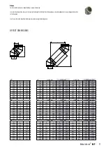
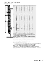


15°
15°
Ø
X
Y
Ø
X
Y
X
Y
X
Y
X
Y
100
36
275
100
62
372
101
517
166
758
286
1207
130
39
295
130
65
391
104
536
168
778
289
1227
150
41
315
150
67
411
106
556
171
798
291
1247
180
44
334
180
70
431
109
576
173
817
294
1266
200
47
354
200
72
450
111
595
176
837
296
1286
250
52
393
250
78
490
116
635
181
876
302
1325
300
52
393
300
78
490
116
635
181
876
302
1325
350
52
393
350
78
490
116
635
181
876
302
1325
400
65
491
400
91
588
129
733
194
974
314
1424
30°
30°
Ø
X
Y
Ø
X
Y
X
Y
X
Y
X
Y
100
70
261
100
120
348
195
478
320
694
552
1097
130
75
280
130
125
367
200
496
325
713
557
1116
150
80
299
150
130
385
205
515
330
732
562
1134
180
85
317
180
135
404
210
534
335
750
567
1153
200
90
336
200
140
422
215
552
340
769
572
1172
250
100
373
250
150
460
225
590
350
806
582
1209
300
100
373
300
150
460
225
590
350
806
582
1209
350
100
373
350
150
460
225
590
350
806
582
1209
400
125
467
400
175
553
250
683
375
900
607
1302
45°
45°
Ø
X
Y
Ø
X
Y
X
Y
X
Y
X
Y
100
99
239
100
170
310
276
416
453
593
781
921
130
106
256
130
177
327
283
433
460
610
788
938
150
113
273
150
184
344
290
450
467
627
795
955
180
120
290
180
191
361
297
467
474
644
803
973
200
127
307
200
198
378
304
484
481
661
810
990
250
141
341
250
212
412
318
518
495
695
824
1024
300
177
427
300
247
497
354
604
530
780
859
1109
350
177
427
350
247
497
354
604
530
780
859
1109
400
191
461
400
262
532
368
638
544
814
873
1143
L= 100 mm
L= 250 mm
L= 500 mm
L= 1000 mm(965)
L= 100 mm
L= 250 mm
L= 500 mm
L= 1000 mm(965)
L= 100 mm
L= 250 mm
L= 500 mm
L= 1000 mm(965)
Ø
x
y
Ø
x
y
L
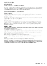
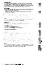
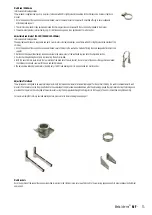
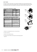
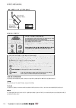
Elbows
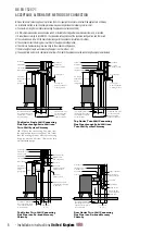
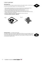
For offset information on standard elbows, please refer below�
In cases of top mounted stoves, a minimum vertical height of 600mm from the appliance is recommended prior to any change of direction
in the flue pipe�
In all cases the joints should be held securely in place using the locking band�
OFFSET DIMENSIONS
11
Metaloterm
®
MF
-


