
NL 2:3 1:1,5
GB 1:2
BE 13:15 1:1,15
FR 2:3 1:1,5
DE
3:5
1:1,7
CH 1:1
IT
2:3
1:1,5
FI 11:18 1:1,64
NO 8:11 1:1,375
LV 1:2
PL 5:8 1:1,6
CZ 2:3 1:1,5
GR 2:3 1:1,5
CY 3:5 1:1,7
SE 10:16 1:1,6
DK 28:37 1:1,32
AT 2:3 1:1,5
HU 1:2
RO 2:3 1:1,5
RS 2:3 1:1,5
BG
3:5
1:1,7
IE 1:2
LU
1:2 (of 3:5)
EG
2:3
1:1,5
NZ 1:2
RU 2:3
MD 1:2
EU 2:3 1:1,5
Land Verhouding
vlag vlag+outline kleurcodes
Vlaggen (v.2015)
C-M-Y-K:
0-84-77-32
C-M-Y-K:
0-0-0-0
Pantone
032-C
C-M-Y-K:
0-0-0-0
C-M-Y-K:
76-50-0-46
C-M-Y-K:
100-72-0-18.5
C-M-Y-K:
0-0-0-0
C-M-Y-K:
0-91-76-6
C-M-Y-K:
100-72-0-18.5
C-M-Y-K:
0-0-0-0
C-M-Y-K:
0-91-76-6
C-M-Y-K:
0-0-0-100
C-M-Y-K:
0-15-95-0
C-M-Y-K:
0-90-80-5
C-M-Y-K:
100-70-0-5
C-M-Y-K:
0-0-0-0
C-M-Y-K:
0-90-86-0
C-M-Y-K:
0-0-0-100
C-M-Y-K:
0-100-100-0
C-M-Y-K:
0-12-100-5
Pantone
144-C
Pantone
336-C
C-M-Y-K:
0-0-0-0
C-M-Y-K:
0-100-100-0
C-M-Y-K:
0-0-0-0
C-M-Y-K:
100-0-100-45
C-M-Y-K:
0-0-0-0
C-M-Y-K:
0-100-100-0
C-M-Y-K:
100-70-0-10
C-M-Y-K:
0-10-95-0
C-M-Y-K:
0-90-80-5
Pantone
186-C
Pantone
116-C
C-M-Y-K:
0-0-0-100
C-M-Y-K:
100-70-0-10
C-M-Y-K:
0-10-95-0
C-M-Y-K:
0-90-80-5
C-M-Y-K:
100-70-0-10
C-M-Y-K:
0-10-95-0
C-M-Y-K:
0-90-80-5
Pantone
347-C
Pantone
151
RGB:
255-255-255
RGB:
0-150-110
RGB:
214-38-18
Pantone
032-C
C-M-Y-K:
0-0-0-0
Pantone
299
C-M-Y-K:
100-56-0-18.5
C-M-Y-K:
0-0-0-0
Pantone Red
032 U
C-M-Y-K:
0-0-0-0
Pantone Red
281 U
C-M-Y-K:
25-96-84-19
C-M-Y-K:
0-0-0-0
Pantone
186-C
C-M-Y-K:
0-0-0-0
C-M-Y-K:
0-0-0-0
Pantone
348-C
#: D4 21 3D
ca.10-96-71-1
#: E9 E8 E7
NCS
0580-Y10R
NCS
4055-R95B
Pantone
281 U
Pantone Red
032 U
C-M-Y-K:
0-0-0-0
C-M-Y-K:
ca.98-99-22-14
C-M-Y-K:
0-0-0-0
Pantone
186-C
C-M-Y-K:
0-0-0-0
C-M-Y-K:
100-80-0-0
C-M-Y-K:
0-0-100-0
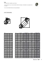
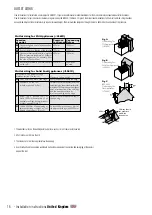
3/2
2/9
1
1
3/2
30°
2/3
DESIGN GUIDE
Mandatory Requirements
Connection to an appliance which is not connected to the fuel supply, should be carried out by a competent person� We recommend the use of HETAS approved installers for
solid fuel applications� If installation is carried out by a non HETAS registered installer, the installation must be certified by a local Building Control inspector� Connection to an
appliance that is connected to the fuel supply must be carried out by a Gas Safe (Gas) or OFTEC (Oil) registered installer�
The design guide must be read in conjunction with the detailed component installation instructions� For full design and installation details the key referral documents are:
• BS EN 1856-1
: Chimneys - System Chimney Products
• BS EN 1856-2
: Connecting Flue Pipes
• BS EN 1859
: Metal Chimneys - Testing Methods
• BS EN 1443
: Chimneys - General Requirements
• BS EN 15287-1
: Chimneys� Design, installation and commissioning of chimneys� Chimneys for non-room sealed heating appliances�
• BS 5440-1
: Fluing and ventilation for gas appliances of rated input not exceeding 70kW net (1st, 2nd and 3rd family gases)�
Specification for installation of gas appliances to chimneys and for maintenance of chimneys�
• Approved Document J
: - Combustion appliances and fuel storage systems (England & Wales)
• DFP Technical Booklet L
: - Combustion appliances and fuel storage systems (NI)
• Technical Handbook (Domestic & Non Domestic), Section 3
- Environment (Scotland)
• Appliance Installation Instructions
and related standards� Other standards covering specific applications will also be relevant and must be adhered to�
Planning permission may be required, and reference should be made to the local Building Control Department�
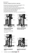
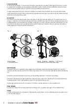
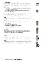
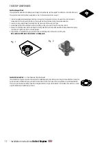
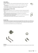
Ensure all chimney components are available and check them to ensure there has been no damage� Do not use damaged components� Build the chimney up through the
previous designed route which should be as straight as possible�
PRIOR TO INSTALLATION
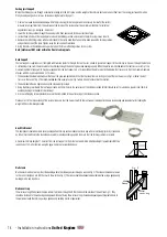
Ventilation
It is very important that sufficient air for combustion and ventilation is provided to the room containing the appliance, to enable correct and efficient working of the appliance
and chimney system� Reference should be made to the appliance manufacturer’s instructions and recommendations are also given in the Building Regulations Document J,
CIBSE guidance notes and BS 5440�
Carbon Monoxide Alarms
The carbon monoxide alarms should comply with BS EN 50291
Where a new or replacement fixed solid fuel appliance is installed in a dwelling, a carbon monoxide alarm must be provided
in the room where the appliance is located�
Please follow manufacturers instructions with regards to siting and fixing or alternatively :-
a) On the ceiling at least 300mm from any wall or if it is located on a wall, as high up as possible (above any doors and windows), but not within 150mm of the ceiling and
b) between 1m and 3m horizontally from the appliance�
N�B Provision of a carbon monoxide alarm should not be regarded as a substitute for correct installation and regular servicing�
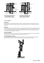
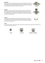
Painting
If painting of any external sections is required, it is important to de-grease, dry and prime the exterior surface prior to the application of appropriate heat resistant paint�
Handling
It is advised that suitable PPE should be used when handling the products�
Delivery to Site and Storage
Components should be carefully transported and off loaded� They should be inspected to ensure they have not been damaged, and should be stored off the ground and under
cover so that they are protected from accidental damage and the adverse effects of weather�
Pools/Coastal areas/etc.
The use of stainless steel systems in an enclosed space where there may be a high concentration of aggressive vapours and acid in the air (such as in swimming pools,
launderettes, etc�) may cause a problem� This also applies to installation in the immediate vicinity of the sea and/or with a view of the sea�
4
- Installation instructions
United Kingdom


