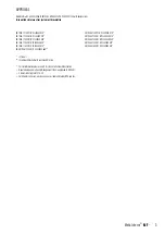
NL 2:3 1:1,5
GB 1:2
BE 13:15 1:1,15
FR 2:3 1:1,5
DE
3:5
1:1,7
CH 1:1
IT
2:3
1:1,5
FI 11:18 1:1,64
NO 8:11 1:1,375
LV 1:2
PL 5:8 1:1,6
CZ 2:3 1:1,5
GR 2:3 1:1,5
CY 3:5 1:1,7
SE 10:16 1:1,6
DK 28:37 1:1,32
AT 2:3 1:1,5
HU 1:2
RO 2:3 1:1,5
RS 2:3 1:1,5
BG
3:5
1:1,7
IE 1:2
LU
1:2 (of 3:5)
EG
2:3
1:1,5
NZ 1:2
RU 2:3
MD 1:2
EU 2:3 1:1,5
Land Verhouding
vlag vlag+outline kleurcodes
Vlaggen (v.2015)
C-M-Y-K:
0-84-77-32
C-M-Y-K:
0-0-0-0
Pantone
032-C
C-M-Y-K:
0-0-0-0
C-M-Y-K:
76-50-0-46
C-M-Y-K:
100-72-0-18.5
C-M-Y-K:
0-0-0-0
C-M-Y-K:
0-91-76-6
C-M-Y-K:
100-72-0-18.5
C-M-Y-K:
0-0-0-0
C-M-Y-K:
0-91-76-6
C-M-Y-K:
0-0-0-100
C-M-Y-K:
0-15-95-0
C-M-Y-K:
0-90-80-5
C-M-Y-K:
100-70-0-5
C-M-Y-K:
0-0-0-0
C-M-Y-K:
0-90-86-0
C-M-Y-K:
0-0-0-100
C-M-Y-K:
0-100-100-0
C-M-Y-K:
0-12-100-5
Pantone
144-C
Pantone
336-C
C-M-Y-K:
0-0-0-0
C-M-Y-K:
0-100-100-0
C-M-Y-K:
0-0-0-0
C-M-Y-K:
100-0-100-45
C-M-Y-K:
0-0-0-0
C-M-Y-K:
0-100-100-0
C-M-Y-K:
100-70-0-10
C-M-Y-K:
0-10-95-0
C-M-Y-K:
0-90-80-5
Pantone
186-C
Pantone
116-C
C-M-Y-K:
0-0-0-100
C-M-Y-K:
100-70-0-10
C-M-Y-K:
0-10-95-0
C-M-Y-K:
0-90-80-5
C-M-Y-K:
100-70-0-10
C-M-Y-K:
0-10-95-0
C-M-Y-K:
0-90-80-5
Pantone
347-C
Pantone
151
RGB:
255-255-255
RGB:
0-150-110
RGB:
214-38-18
Pantone
032-C
C-M-Y-K:
0-0-0-0
Pantone
299
C-M-Y-K:
100-56-0-18.5
C-M-Y-K:
0-0-0-0
Pantone Red
032 U
C-M-Y-K:
0-0-0-0
Pantone Red
281 U
C-M-Y-K:
25-96-84-19
C-M-Y-K:
0-0-0-0
Pantone
186-C
C-M-Y-K:
0-0-0-0
C-M-Y-K:
0-0-0-0
Pantone
348-C
#: D4 21 3D
ca.10-96-71-1
#: E9 E8 E7
NCS
0580-Y10R
NCS
4055-R95B
Pantone
281 U
Pantone Red
032 U
C-M-Y-K:
0-0-0-0
C-M-Y-K:
ca.98-99-22-14
C-M-Y-K:
0-0-0-0
Pantone
186-C
C-M-Y-K:
0-0-0-0
C-M-Y-K:
100-80-0-0
C-M-Y-K:
0-0-100-0
3/2
2/9
1
1
3/2
30°
2/3
24
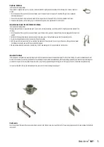
Guy Wire Bracket
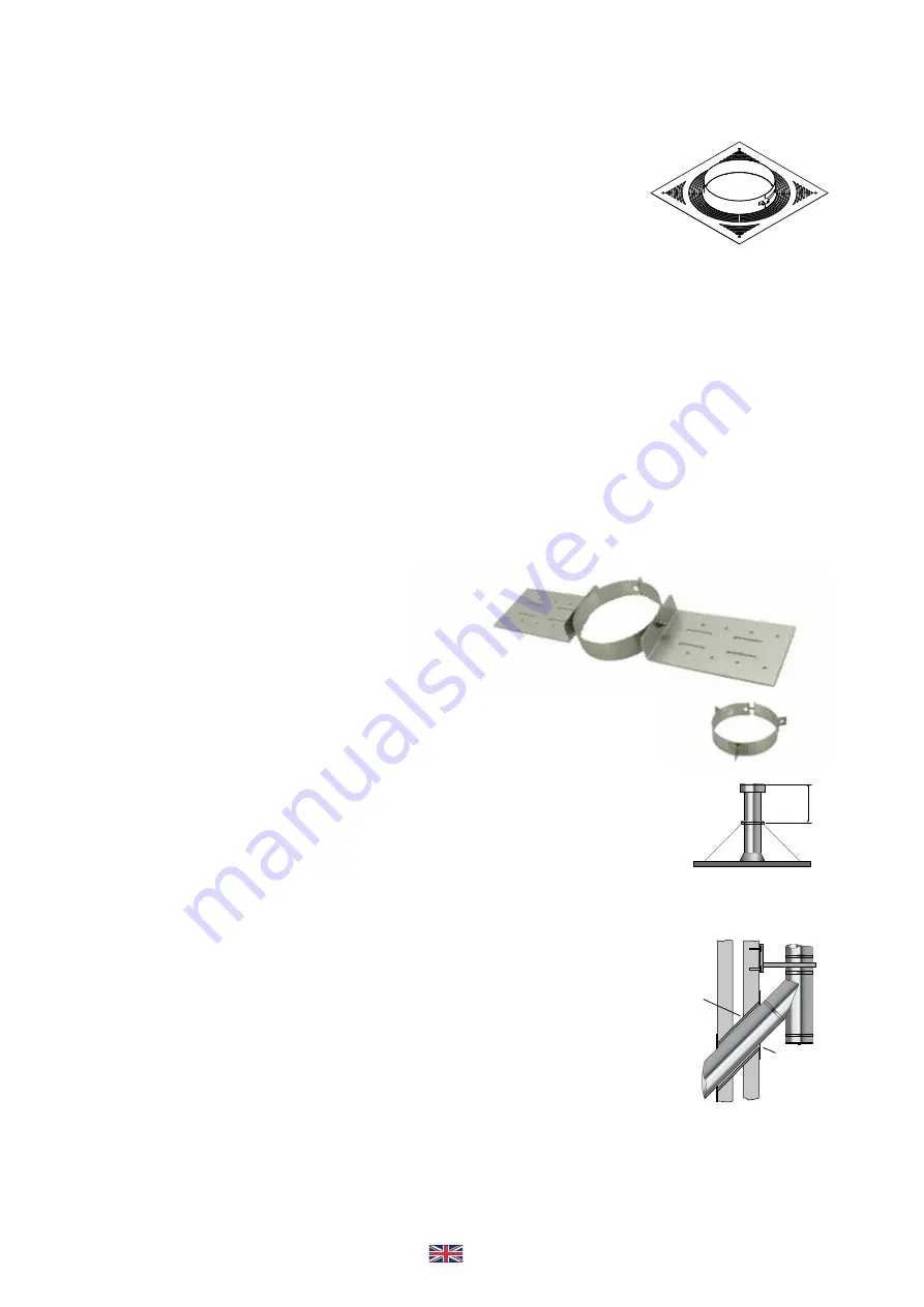
This component should be used to secure unsupported chimney sections above
roof level. Guy wires or preferably rigid stays (supplied by others) must be fixed to
the bracket and secured to suitable anchorage points to ensure that the chimney
sections are stable.
A maximum chimney height of 1.5 metres from the last support, or from the roof
is permitted. Additional height requirements MUST be supported at 1.5 metre
intervals using the guy wire bracket as specified above.
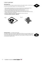
Ceiling Hanger
This accessory is designed to support horizontal runs of the chimney from the
roof or ceiling and offers adjustment from 130mm to 1115mm.
Once the position of the ceiling support has been determined, the section
length of uni-rax channel must be securely fixed to the roof or the ceiling using
a method of attachment to ensure adequate attachment and support.
All items are assembled as shown to attach the length of studding to the channel.
Attach the stud connector to the length of studding and connect the eye bolt
to the connector.
Position the split band around the chimney section and secure to the eye bolt
using the nut/bolt provided.
Maximum support spacing to be no more than 1.5 metres.
1.
2.
3.
4.
5.
Guy Wire Bracket
Ceiling Hanger
Guy Wire
Rigid Stay
1.5 metres
maximum
Fig. 1
Fig. 2
Wall
Sleeve
Wall
Sleeve
Wall
cover ring
D
A
B
Ø 6,5
25
25
Ø 100 130 150 180 200 250
D 156 186 206 236 256 306
A 350 380 400 430 450 500
B 250 280 300 330 350 400
MFCSP
Ventilated Ceiling Support
Belüftete Geschoßkonsole
Support Au Plafond Ventilé
Geventileerde Verdiepingsondersteuning
Ceiling Joist Support
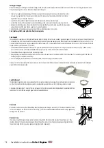
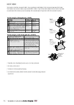
Where the chimney passes through a combustible ceiling into the roof space, and the weight of the chimney has to be taken at floor level� The ceiling joist support must be
firmly fixed by using bolts or screws� For load bearing Data refer to page 17�
1� Frame a four sided level square opening within the joists using timber stringers where necessary to allow for the correct
distance to combustibles from the outer wall of the chimney� This distance must be a minimum of 60mm for solid fuel
applications (see Fig� 3 alongside - distance x)�
2� Lower the chimney section through the opening in the floor, and secure to the next section of pipe�
3� Locate the two halves of the support plates around the chimney section, and secure to the joists using screws or bolts�
4� Remove the self-drilling screws which are fastened to the clamp band�Then fasten clamp band around the chimney section
and position on top of the plate� Tighten using the nuts and bolts provided�
5� Using the holes in the clamp band as a guide, fasten the three self-drilling screws to the system�
Note: Joints must NOT occur within the floor or ceiling joists
Roof Support
The roof support is supplied as a kit complete with two side plates for fixing to the roof trusses, a band to give lateral support to the chimney as it passes through the roof, and
3 self tapping screws, which are secured to the chimney through the band to give a load bearing capacity� When the plates are installed above the roof trusses as in Fig�1 the
maximum number of pipes, which may be suspended from the roof support is 6 x 1m pipes� When the plates are attached below the trusses as in Fig�2 the maximum number
of pipes, which may be suspended is 4 x 1m pipes�
1� The band should be lowered down over the top of the pipe, and positioned so that the the side plates are resting on top of the roof trusses as in Fig�1 or below the roof
trusses in the case of Fig� 2� The recommended position is always as per Fig�1 where circumstances allow this solution�
2� The band should then be tightened using the nut and bolt provided�
3� Using the holes pre-drilled in the roof support band, drill 3mm holes in the outer case of the chimney section (drill bit should be set for a depth no greater than 10mm to
avoid any damage to the liner of the chimney)
4� Use the self tapping screws provided to secure the clamp band to the outer casing of the chimney section�
Please note: It is the responsibility of the installer to ensure that the trusses to which the roof support is being attached are load bearing and capable of withstanding the
weight of the system being installed�
Guy Wire Bracket
This component should be used to secure unsupported chimney sections above roof level� Guy wires or preferably rigid stays (supplied
by others) must be fixed to the bracket and secured to suitable anchorage points to ensure that the chimney sections are stable�
A maximum chimney height of 1�5 metres from the last support, or from the roof is permitted� Additional height requirements MUST be
supported at 1�5 metre intervals using the guy wire bracket as specified above�
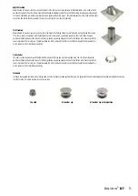
Wall sleeve
Wall sleeves must be used to protect the building where the chimney passes through a wall (see Fig� 2)� The sleeve should be cut down
to the correct length on site to fit flush with the wall (see Fig� 2)� The sleeve should be adequately weatherproofed, using a good quality
building mastic and rope fibre�
Wall cover ring
The wall cover ring fitted around the pipe where it protrudes through both the inside and the outside of the wall (see Fig� 2)� They
should be fastened to the wall using an adequate method of fixing� The wall cover ring should be adequately weatherproofed back to
the wall and around the chimney, using a good quality building mastic or equivalent�
14
- Installation instructions
United Kingdom

