


NL 2:3 1:1,5
GB 1:2
BE 13:15 1:1,15
FR 2:3 1:1,5
DE
3:5
1:1,7
CH 1:1
IT
2:3
1:1,5
FI 11:18 1:1,64
NO 8:11 1:1,375
LV 1:2
PL 5:8 1:1,6
CZ 2:3 1:1,5
GR 2:3 1:1,5
CY 3:5 1:1,7
SE 10:16 1:1,6
DK 28:37 1:1,32
AT 2:3 1:1,5
HU 1:2
RO 2:3 1:1,5
RS 2:3 1:1,5
BG
3:5
1:1,7
IE 1:2
LU
1:2 (of 3:5)
EG
2:3
1:1,5
NZ 1:2
RU 2:3
MD 1:2
EU 2:3 1:1,5
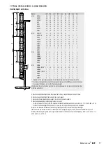
Land Verhouding
vlag vlag+outline kleurcodes
Vlaggen (v.2015)
C-M-Y-K:
0-84-77-32
C-M-Y-K:
0-0-0-0
Pantone
032-C
C-M-Y-K:
0-0-0-0
C-M-Y-K:
76-50-0-46
C-M-Y-K:
100-72-0-18.5
C-M-Y-K:
0-0-0-0
C-M-Y-K:
0-91-76-6
C-M-Y-K:
100-72-0-18.5
C-M-Y-K:
0-0-0-0
C-M-Y-K:
0-91-76-6
C-M-Y-K:
0-0-0-100
C-M-Y-K:
0-15-95-0
C-M-Y-K:
0-90-80-5
C-M-Y-K:
100-70-0-5
C-M-Y-K:
0-0-0-0
C-M-Y-K:
0-90-86-0
C-M-Y-K:
0-0-0-100
C-M-Y-K:
0-100-100-0
C-M-Y-K:
0-12-100-5
Pantone
144-C
Pantone
336-C
C-M-Y-K:
0-0-0-0
C-M-Y-K:
0-100-100-0
C-M-Y-K:
0-0-0-0
C-M-Y-K:
100-0-100-45
C-M-Y-K:
0-0-0-0
C-M-Y-K:
0-100-100-0
C-M-Y-K:
100-70-0-10
C-M-Y-K:
0-10-95-0
C-M-Y-K:
0-90-80-5
Pantone
186-C
Pantone
116-C
C-M-Y-K:
0-0-0-100
C-M-Y-K:
100-70-0-10
C-M-Y-K:
0-10-95-0
C-M-Y-K:
0-90-80-5
C-M-Y-K:
100-70-0-10
C-M-Y-K:
0-10-95-0
C-M-Y-K:
0-90-80-5
Pantone
347-C
Pantone
151
RGB:
255-255-255
RGB:
0-150-110
RGB:
214-38-18
Pantone
032-C
C-M-Y-K:
0-0-0-0
Pantone
299
C-M-Y-K:
100-56-0-18.5
C-M-Y-K:
0-0-0-0
Pantone Red
032 U
C-M-Y-K:
0-0-0-0
Pantone Red
281 U
C-M-Y-K:
25-96-84-19
C-M-Y-K:
0-0-0-0
Pantone
186-C
C-M-Y-K:
0-0-0-0
C-M-Y-K:
0-0-0-0
Pantone
348-C
#: D4 21 3D
ca.10-96-71-1
#: E9 E8 E7
NCS
0580-Y10R
NCS
4055-R95B
Pantone
281 U
Pantone Red
032 U
C-M-Y-K:
0-0-0-0
C-M-Y-K:
ca.98-99-22-14
C-M-Y-K:
0-0-0-0
Pantone
186-C
C-M-Y-K:
0-0-0-0
C-M-Y-K:
100-80-0-0
C-M-Y-K:
0-0-100-0
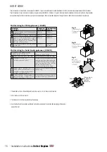
3/2
2/9
1
1
3/2
30°
2/3
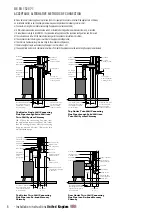
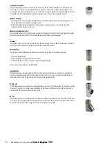
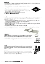
Reinforced Locking Band
The reinforced locking band, which is purchased separately, is used instead of a standard locking band in a situation where extra
structural support is required, for instance where the chimney height is >1�5m above the last support or above the roof� It is also
used to provide extra support in long horizontal runs� A maximum of 3m unsupported height can be achieved by fitting the reinforced
locking band on the joint immediately below and on every joint above the last support� Please see diagram on page 17�
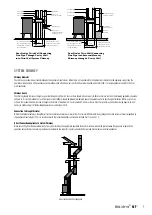
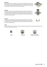
Appliance Connector
1� The protruding liner of these components should be pushed into the appliance spigot with the male collar pointing upwards� The
liner can be trimmed to suit the depth of the appliance spigot�
2� On solid fuel appliances the appliance connector should be sealed to the appliance with fire rope and fire cement or high
temperature sealant to provide a gas tight joint�
Adaptors from single wall to MF
These components are used to convert from a single wall connecting flue pipe to the system chimney� The protruding liner should be
pushed down inside the female socket of the connecting flue pipe, with the male collar pointing upwards�
Increaser
This component is used to increase from one diameter to the next diameter (e�g�) 130mm to 150mm� The component is fitted in the
same way as a standard pipe length and should be secured with the locking band provided�
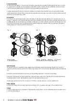
Adjustable Pipes
They are used with standard components to achieve an exact length on site and avoid on-site cutting of components�
1� Calculate the length required�
2� Remove insulation as required to achieve the correct length�
3� Fix the adjusted section to standard components using the locking band provided�
Please note that the adjustable pipe is non load bearing�
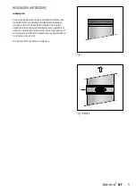
Inspection Pipe
The inspection length is a component providing the facility for flue inspection and cleaning� It is installed as per a standard pipe
section� The removable inspection door must be parallel with the front of the stove, or at least 3 x the internal diameter from any
combustible material (125mm I/D door must be at least 450mm from combustible material)�
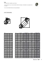
87°/90° Tee
This component may be used to connect from a connecting flue pipe to the vertical system chimney at 90° or the branch may be used
to locate a draft stabiliser� It is installed as per a standard pipe section� Please note that there are no barbs on the female collar in
order to allow for the tee to be positioned at the correct angle�
45° Tee
This component may be used in combination with a 45° elbow to connect from a connecting flue pipe to the vertical system chimney�
It is installed as per a standard pipe section and provides the least resistance to the flow of the flue gases� Please note that there are
no barbs on the female collar in order to allow for the tee to be positioned at the correct angle�
10
- Installation instructions
United Kingdom


