BSK-EN fire damper
INSTALLATION, MOUNTING AND OPERATING INSTRUCTIONS
Models and dimensions
Construction subject to change
No return possible
Version: 2018-11-14 | Page 4
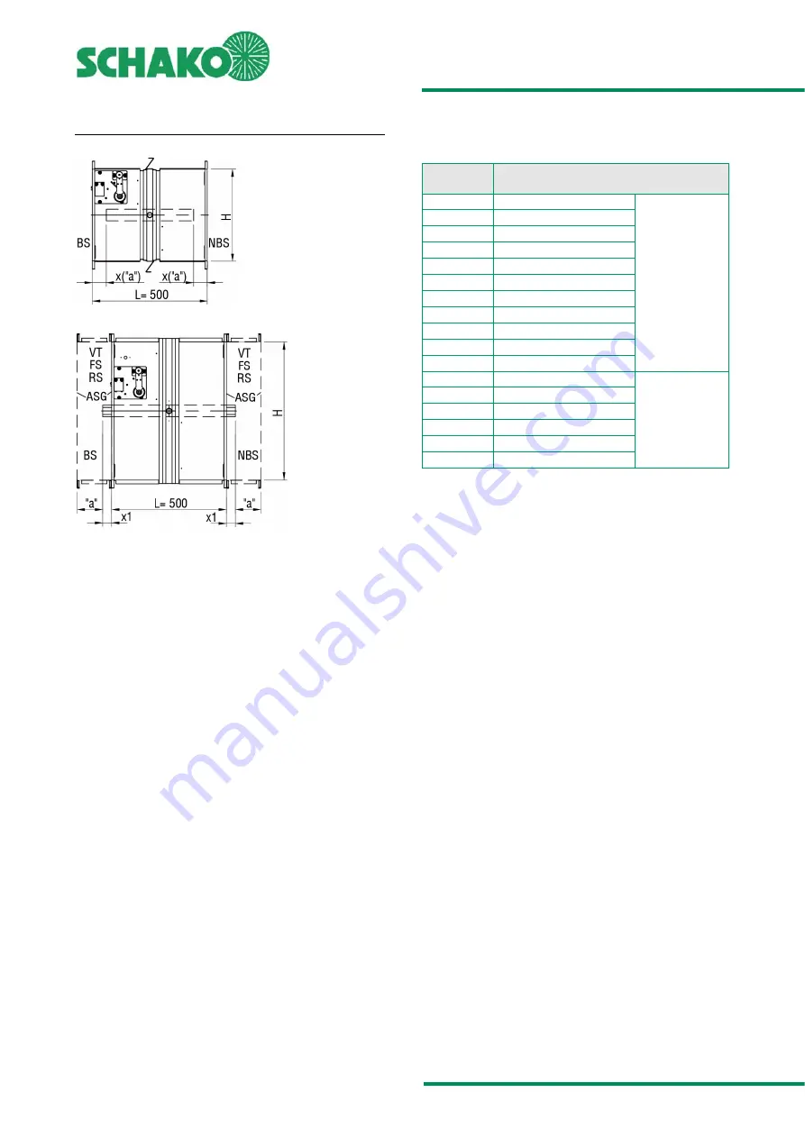
DAMPER LEAF PROJECTING ENDS
Figure 3: Damper leaf projecting ends
BS:
Operating side
NBS
Non-operating side
ASG
Finishing protective grating
VT
Extension part
FS
Flexible connecting piece
RS
Pipe connecting piece
"a" = 50 mm:
Minimum distance between the front
edge of the open damper leaf and the fi-
nishing protective grating (ASG), flexible
connecting piece (FS) or pipe connecting
piece (RS).
H [mm]
Operating side (BS)
Non-operating side (NBS) [mm]
200
160
x
225
148
250
135
275
123
300
110
325
98
350
85
375
73
400
60
(1)
450
35
(2)
500
10
(2)
550
15
(2)
x1
600
40
(2)
650
65
(2)
700
90
(2)
750
115
(2)
800
140
(2)
Table 2: Damper leaf projecting ends
(1)
Extension part (VT) on the operating side (BS) necessary
(2)
Extension part (VT) on both sides necessary


