Quanta series
– Hardware Manual
QUANTAHM.1.2
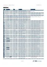
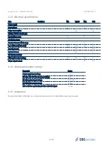
Item
Conditions
Min
Typical
Max
Unit
Input resistance
120
Ω
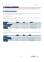
RS-422 transmitters
Differential output voltage
1.5
2.2
3.3
V
Driver output current
60
mA
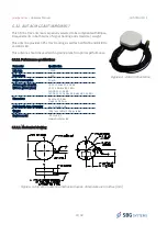
3.3.3. GNSS antenna connectors
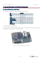
The GNSS antenna connectors are located on the bottom of the GNSS receiver module.
The connector type is UFL. Main antenna should be connected to ANTA and secondary antenna should be
connected to ANTB.
3.4. Reference design
3.4.1. Power supply
To power supply Quanta module, It is recommended to select a power supply with 1500mA average and 2000mA
peak current capabilities in 5.0V.
Note that optimal power consumption is obtained at 5.0V input.
3.4.2. Serial ports connection guidelines
As Quanta hardware delivers LVTTL inputs and outputs, the serial interfaces should be driven to an appropriate
transceiver in case of communication with external equipment. Low distance communication can be performed in
LVTTL format. Some serial ports have specific functions that are described below.
19/48
Figure 3.3: Example of power supply schematic
C20
10uF
C21
10uF
L1
MPZ2012S102AT000
R16
100k
R18
28k
C27
2.2nF
C28
1uF
R21
60.4k
C23
100nF
L2
IHLP2525CZER100M11
C26
10pF
C24
47uF
C25
47uF
6
BIAS
14
FB
16
SW
9
BOOST
12
GND
BIAS
FB
SW
BOOST
GND
PG
15
INTVCC
13
RT
3
VIN
SW
11
TR/SS
2
SYNC
1
SW
10
EN/UV
4
5
LT8610ABEMSE#PBF
R20
88.7k
R19
374k
Vin 6 - 36 V
VDD_+5V
VIN
Figure 3.2: GNSS Antenna connectors


