Quanta series
– Hardware Manual
QUANTAHM.1.2
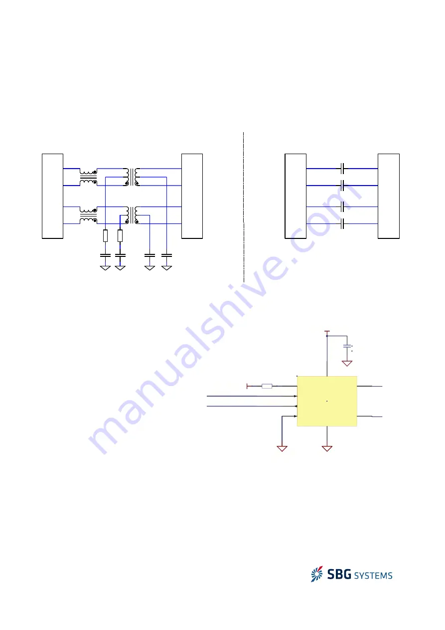
3.4.3. Ethernet interface
The micro module can be interfaced with other Ethernet peripherals in different ways.
When the connection involves a long distance communication (typically, when there is a cable), the first
implementation is required. When the device is located on the same electronic board, it is possible to select an
easy circuit with capacitors.
3.4.4. CAN bus
The processing micro module does not
integrate a CAN bus driver. Therefore, a
driver integration is required in case the CAN
bus output is used in user application. The
following schematic shows a typical driver
integration:
21/48
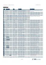
Figure 3.5: CAN bus interface reference design
TXD
1
2
3
RXD
4
STBY
8
VCC2
5
CANH
7
CANL
6
VCC
GND
U7
MAX1
R19
0
isoCAN.TX
isoCAN.RX
C33
100nF
isoGND_CAN
5V_CAN
isoGND_CAN
5V_CAN
1
2
3
4
8
5
TXD
RXD
STBY
VCC2
CANH
7
CANL
6
VCC
GND
U7
MAX1
R19
0
isoCAN.TX
isoCAN.RX
C33
100nF
isoGND_CAN
isoGND_CAN
i5V_CAN
isoGND_CAN
5V_CANN
CAN_H
CAN_L
Figure 3.4: Ethernet interface implementation
RXP
RXM
RXM
RXP
TXM
TXP
RXM
RXM
RXP
TXM
TXP
RXM
Processing
Micro-Module
Host IC
Ethernet
CATx Cable
Processing
Micro-Module
2x
10nF, 16V
2x
1nF, 1kV
2x
75Ω, 0.25W
4x
10nF, 25V
Ethernet cable Interface circuit
Host IC Interface circuit
2x
CMM Choke
2x
Isolation Transformer
TXM
TXP
RXP
RXM
TXM
TXP

