MIS_100
Data di emissione 11/06/2015
Pag.12 di 32
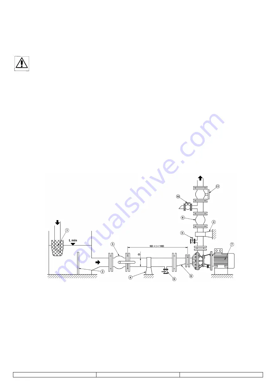
Plant (ref to fig. 1)
General recommendations:
-
the pump performance is negatively affected by the on-off or non-return valves with high head losses, by tight curves, by
pipe diameters smaller than the pump suction and delivery openings, by non cone-shaped, concentric diameter reduction
(in delivery) or by non-eccentric, if necessary in suction.
-
delivery pipes:
-
the pump must never work or start-up with the discharge valve completely closed,
rather, if it is designed
for a very small output, it requires the installation of a by-pass (10) - for the partial recycle of liquid in the tank -
before the control valve (11): the by-pass avoids a temperature increase of the fluid inside the pump casing;
-
it might be necessary to fit a non-return valve (9) on the delivery pipe, between the pump (7) and the control
valve (11); this is done to avoid the “water hammer” or due to other requirements;
-
if the pump is installed under-head, with the non-return valve in delivery (9), it is necessary to install an air
discharge valve (8) between the pump (7) and the non-return valve (9), in order to ensure adequate priming.
-
suction pipes:
-
diameter between 1 and 1,5 times the diameter of the pump suction opening with eccentric reduction (6) on
pump side, if necessary, to avoid the possibility of air pockets creating problems of priming;
-
horizontal (better if slightly descending towards the pump), straight and of the shortest possible length (between
5 and 10 times the pipe diameter): if a longer length and/or curve are required, the pipe must have a greater
diameter and the curve must be a bend (not an elbow);
-
avoid a suction filter, whose inadequate maintenance damages the pump; it is better to sift (1) the liquid either at
the tank input or with a screen (2) fitted at suitable distance from the pump suction inlet;
-
provide for an on-off valve (3) (never for a control valve) between the pump and the tank, to ensure
maintenance and ease emergency operations, and a draining valve (5) for the pump and the tank.
-
switch of minimum level:
the pump must never work in dry conditions and the pump casing
– after initial filling (ref. to 4.1.8 and
9.4),
must be kept completely full with liquid at all times
: therefore, it is indispensable to install an efficient
control of the liquid minimum level in the tank, that prevents input of air from the pump suction and ensuring that
the pump is always filled-up with liquid (ref to fig. 1).
-
recovery of the draining liquid from the pump and plant:
there must be a provision for a tank, channels or any other suitable recovery system of the liquid that could
come out from the pump either due to the malfunctioning of the mechanical seal or drained by the pump and/or
by the plant during maintenance.
Fig. 1
___________________________________________________________________________________________________________
9.7 Strumentazione
Per la corretta gestione della pompa rispetto ai dati di progetto suoi e dell’impianto e delle esigenze di sorveglianza e di
manutenzione sono necessari:
-
manometro e flussimetro (valori di pressione e di portata):
installati sull’impianto prima della valvola di regolazione con
eventuale by-pass;
-
tester per il controllo dell’isolamento degli avvolgimenti del motore elettrico e della corrente assorbita durante il suo
funzionamento;
-
fonometro per la misura, quando richiesto, della pressione e/o della potenza acustica emessa dalla macchina nelle
specifiche condizioni ambientali;
-
apparecchiature più sofisticate molto utili per il monitoraggio della pompa, utilizzabili se disponibili, sono le sonde
accelerometriche nel campo delle basse frequenze (10 Hz ÷1 kHz), per la misura della vibrazione globale della
macchina, e nel campo delle alte frequenze (10 kHz ÷ 30 kHz) per la rilevazione delle condizioni operative dei cuscinetti.


