ASV115
Very simple parameterisation of complex applications
Uploading and downloading parameters to transfer configurations
from one device to another
Configurable units range
Overview page for rapid entry of the main parameters
Tree view for fast navigation through the individual configuration
pages
Integrated access to plant schematic and wiring diagram
Print-out of device configuration
Service functions for fast troubleshooting
C
C
C
A
1
0
640
Device No. 31 (max.)
120
(L > 200 m)
120
(L > 200 m)
Shielding
Control cabinet
Device No. 1
MM
MM
24V~
Device No. 2
Structured user guidance
Online monitoring of most important operation parameters
Engineering and fitting notes
The drive can be fitted in any position (including upside down). It is
placed directly on the damper shaft and clipped to the anti-torque
device. The self-centring shaft adaptor ensures gentle operation of
the damper shaft. The damper drive can be easily removed from
the damper shaft without dismantling the anti-torque device.
The angle of rotation can be limited between 0° and 90° on the
device and can be set continuously between 5° and 80°. The limita-
tion is set with a set-screw directly on the drive, and with the limit
stop on the self-centring shaft adaptor. This shaft adaptor is suitable
for damper shafts of Ø 8...16 mm,
6.5...12.7 mm.
Note
The housing must not be opened.
For feedback of the operating status, it is advisable to display the
actual value signal (air volume) in the management system.
No account has been taken of special standards such as
IEC/EN 61508, IEC/EN 61511, IEC/EN 61131-1 and 2. Local regu-
lations on installation, application, access, access authorisations,
accident prevention, safety, dismantling and disposal must be
observed. Compliance is also required with installation standards
EN 50178, 50310, 50110, 50274, 61140 and similar.
The RS-485 parameterisation interface in the housing cover is not
suitable for continuous operation. After parameterisation has been
completed, the parameter plug must be removed and the opening
should be sealed to restore the IP protection type.
Fitting outdoors
We recommend that devices are given additional protection against
the effects of weather if installed outside.
Wiring
Power supply
To ensure fault-free operation, the following wire cross-sections and
lengths must be observed for the 24 V power supply and the ground
connection.
All devices within a network segment must be supplied by the same
transformer. The power supply should be wired in star formation,
observing the max. cable length in accordance with the table below
(column 1:
1 Device
).
Maximum cable lengths for various numbers of devices
Maximum number of devices
Cross-
section
1* 8 16 24
32
0.32 mm²
50
6.2
3.2
2.0
1.6
0.5 mm²
80
10.0
5.0
3.4
2.6
0.75 mm²
120
05.0
7.6
5.0
3.8
1.00 mm²
160
20.0
10.0
6.6
5.0
1.50 mm²
240
30.0
15.0
10.0
7.6
*) Star formation recommended.
Analogue signals
Analogue and digital signals are connected via the power cable. To
ensure perfect operation, the ground cable (for drives that are
interconnected in order to exchange signals) must be on the same
potential.
The maximum cable length for analogue signals is dependent
mainly on the voltage drop on the ground cable. A signal cable with
a resistance of 100
results in a 10 mV voltage drop with an
ASV115 connected. If ten ASV115s are connected to this cable in
series, the resultant voltage drop is 100 mV or an error of 1%.
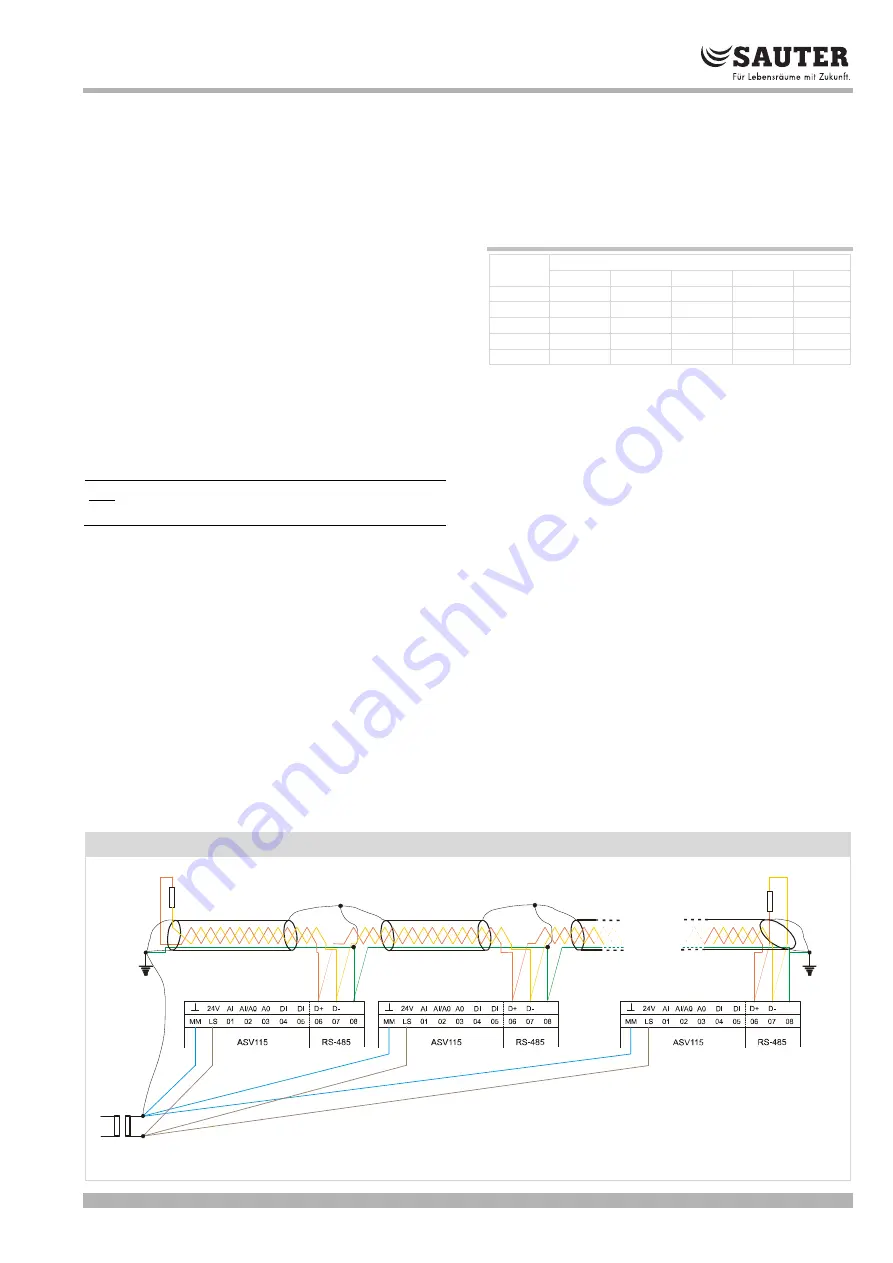
SLC bus connection
The integrated SLC bus is physically specified as an RS-485 inter-
face. Depending on the line length, up to 31 devices can be con-
nected within one network segment. On all the controllers, the
terminals C08 should be linked together and have the same poten-
tial. Neither special cables nor terminating resistors are required for
cabling < 200 m. The wiring should have a purely line topology
(daisy chain). Stub cables are not permitted; however, if they can-
not be avoided, they should be limited to a maximum of 3 metres.
Wiring diagram (SLC bus)
www.sauter-controls.com
7/13


