background image

SATEL 

INTEGRA 128-WRL 

INT-GSM LTE. LTE communication module.

 Enables reporting events as well as operating 

and programming the alarm control panel via the cellular data network 
(LTE/HSPA+/EDGE/GPRS). 

The  INT-GSM  / INT-GSM LTE  module can be connected to the keypad bus of the 
control panel or to the RS-485 bus of the ETHM-1 Plus module.  If the ETHM-1 Plus 
module is connected to the control panel, it is recommended that the INT-GSM  / 
INT-GSM LTE module be connected to the RS-485 bus of the ETHM-1 Plus module. 

INT-RS / INT-RS Plus. Interface for systems integration.

 Makes it possible to connect the 

computer with the GUARDX  program, report events through a special external device, 
or operate the control panel using software other than that offered by SATEL. 

4.2  Modules to be connected to the expander bus 

INT-RX  / INT-RX-S.  433 MHz keyfobs receiver expansion module.

  Enables  operation of 

the alarm system using the 433 MHz keyfobs. 

INT-CR. Proximity card arm/disarm device.

 Enables arming / disarming and alarm clearing 

in many partitions by means of proximity cards, proximity tags and other passive 
transponders. 

INT-S / INT-SF / INT-SK. Partition keypad.

 Enables arming / disarming and alarm clearing 

in one partition. Can perform access control functions. 

INT-SCR. Multifunctional keypad.

 It can work as: 

INT-S. Partition keypad.


INT-SCR.  Partition keypad with reader. 

Functionality similar to that of the partition 

keypad. 

INT-ENT. Entry keypad. 

It allows the user to activate delay for the 3. I

NTERIOR DELAYED


type zones. After expiry of the time period preset on the keypad, unless the 
system is disarmed, the interior delayed zones will again act as instant ones. 

INT-SZ / INT-SZK. Code lock.

 Enables performance of the access control functions. 

INT-R. Universal expander for card / chip readers.

  Supports the proximity card readers 

manufactured by SATEL, readers with WIEGAND 26 interface or DALLAS chip readers. 
Enables performance of the access control functions. 

INT-E / CA-64 E / CA-64 EPS. 

Ekspander  wejść.


Umożliwia  rozbudowę  systemu  o  8 

programowalnych wejść przewodowych.


INT-ADR / CA-64 ADR. Addressable zone expander.

  Adds 48 addressable zones to the 

security system. Control panels support the addressable zone expanders with firmware 
version 1.5 (or later). 

INT-O / INT-ORS / CA-64 O / CA-

64  OPS.  Ekspander  wyjść.


Umożliwia  rozbudowę 

systemu o 8 programowalnych wyjść przewodowych.


INT-PP / INT-IORS / CA-

64 PP. Ekspander wejść i wyjść.


Umożliwia rozbudowę systemu 

8 programowalnych wejść i wyjść przewodowych.


ACU-

220 / ACU-280. 

ABAX 2 wireless system controller.

  Enables the alarm system to 

be operated using the ABAX 2 keyfobs and the ABAX 2 bidirectional wireless devices to 
be used in the alarm system.


ACU-120 / ACU-270 / ACU-100 / ACU-250. ABAX wireless system controller.

 Enables the 

alarm system to be operated using the ABAX 2 / ABAX keyfobs and the ABAX 2 / ABAX 
bidirectional wireless devices to be used in the alarm system. 

INT-VG. Voice module.

  Allows remote operation of the control panel from the telephone 

keypad (interactive voice menu). It can store 16 voice messages for telephone 
messaging. 

Содержание Integra 128-WRL

Страница 1: ...INSTALLER MANUAL SATEL sp z o o ul Budowlanych 66 80 298 Gda sk POLAND tel 48 58 320 94 00 www satel eu integra wrl_i_en 08 21 Alarm Control Panels INTEGRA 128 WRLFirmware version 1 20...

Страница 2: ...under the warranty SATEL aims to continually improve the quality of its products which may result in changes in their technical specifications and software Current information about the changes being...

Страница 3: ...ware version 1 20 Keypads Support for new keypads INT TSG2 and INT TSH2 Outputs New option AC LOSS FAST for the 28 AC LOSS MAINBOARD IMMEDIATE type outputs Reporting New option for the SIA IP format E...

Страница 4: ...essing devices connected to the expander bus 18 5 7 Connecting the detectors 18 5 7 1 End of line resistors 19 5 8 Connecting the sirens 20 5 9 Connecting power supply 20 5 9 1 Main power supply 20 5...

Страница 5: ...of end of line resistors several dozen zone types Maximum number of programmable zones 128 Outputs 8 programmable hardwired outputs on the control panel mainboard 2 high current outputs 6 low current...

Страница 6: ...ging to 16 phone numbers in the form of 16 voice messages played back by an additional module INT VG CA 64 SM or SM 2 64 text messages defined by the installer PAGER or SMS Event log 21503 events A se...

Страница 7: ...modem serial printer connection for printing current events Capability of the firmware updating without the need for disassembly of the control panel Socket for connecting the INT VG voice module CA...

Страница 8: ...he status of the partitions and the system Backlit keys Built in sounder 2 programmable hardwired zones support for NO and NC detectors support for Single EOL and Double EOL configuration Tamper prote...

Страница 9: ...keypad It allows the user to activate delay for the 3 INTERIOR DELAYED type zones After expiry of the time period preset on the keypad unless the system is disarmed the interior delayed zones will ag...

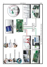
Страница 10: ...8 Installer Manual SATEL Fig 1 INTEGRA 128 WRL security alarm system...

Страница 11: ...motion detector APD 100 wireless passive infrared detector APMD 150 wireless dual motion detector ARD 100 wireless reorientation detector ASD 110 wireless smoke and heat detector ASD 150 wireless smo...

Страница 12: ...2 5 mm Phillips screwdriver precision pliers flat nose pliers driller c w a set of drill bits 5 1 Installation plan The installation must be preceded by preparation of a plan of the security alarm sy...

Страница 13: ...device should not exceed 1 V as against the output voltage In order to guarantee correct functioning of the system components it is important that resistance and capacitance of the signal wires be as...

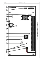
Страница 14: ...ns for Fig 2 battery connection cables red black LEDs indicating the status of high current outputs pins for setting battery charging current pins shorted jumper on 400 mA pins open no jumper 800 mA C...

Страница 15: ...SATEL INTEGRA 128 WRL 13 Fig 2 Control panel mainboard version 2 1...

Страница 16: ...dicating the status of low current outputs socket for connecting the INT VG voice module INT AV audio alarm verification module CA 64 SM voice synthesizer expander or SM 2 synthesizer socket for GSM G...

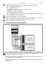
Страница 17: ...to set correct individual addresses in the keypads and perform identification of all devices connected to the bus In other devices to be connected to the keypad bus the address is to be set using the...

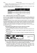
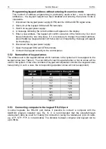
Страница 18: ...keypad CKM and DTM terminals 8 Connect the keypad correctly to the control panel 5 5 2 Numeration of keypad zones The address set in the keypad defines which numbers in the system will be assigned to...

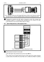
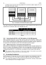
Страница 19: ...with GUARDX program is connected Data exchange with the computer will begin automatically as soon as the GUARDX program is started 5 6 Connecting devices to the expander bus Fig 6 Connection of module...

Страница 20: ...e connected to the dedicated socket on the control panel electronics board 5 6 2 Addressing devices connected to the expander bus Each device to be connected to the expander bus must have its own indi...

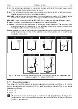
Страница 21: ...zone will also accept connection of a detector with the NC alarm output e g a shock detector and a magnetic contact can be connected in series Follow output in case of this configuration the detector...

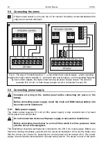
Страница 22: ...e battery Before connecting power supply insert the clock and RAM backup battery into its socket on the mainboard 5 9 1 Main power supply The control panel requires 18 V AC 10 power supply Using a tra...

Страница 23: ...panel electronics board 4 Connect the battery to the dedicated leads positive terminal to RED lead negative terminal to BLACK lead The control panel will not start after connecting the battery alone I...

Страница 24: ...e identified device with another one having the same address will trigger a tamper alarm 5 11 Emergency procedure of the control panel start up If the control panel fails to start properly keypads are...

Страница 25: ...ansmit data over the cellular network it is recommended that you use SIM cards with a dedicated tariff plan for M2M machine to machine communication Having started the control panel you can start up t...

Страница 26: ...re wireless devices The number of positions on the list is at the same time the number of zones and in case of some devices also outputs which will be taken by the device in the system When adding and...

Страница 27: ...d unavailable 5 AMD 100 detector 21 AMD 100 detector 21 unused unavailable 6 AMD 100 detector 22 AMD 100 detector 22 unused unavailable 7 AMD 101 detector 23 AMD 101 detector 23 unused unavailable 8 2...

Страница 28: ...battery into the device turn on the device power etc 5 Type and serial number of the device will be displayed if a message is displayed instead to inform you that the entered serial number is invalid...

Страница 29: ...s will be displayed 3 Use the and keys to select the zone to which the device you want to remove is assigned 4 Press 5 Press the key 1 to confirm that you want to remove the device pressing another ke...

Страница 30: ...el computer with DLOADX program required or remote administration of the security alarm system computer with GUARDX program required The communication is encrypted The control panel can work with any...

Страница 31: ...arameters to be programmed see example in Fig 14 The parameter block saved as the profile 0 in Fig 14 STORED PROFILE 0 should include E1 Q0 V1 X4 D2 S0 and S00 000 In such a case the modem is ready fo...

Страница 32: ...ne containing up to 80 characters or extended format with names of zones partitions users and modules then the event is printed in two lines when the printer with up to 80 characters per line is used...

Страница 33: ...d The same rules apply to the wireless outputs the numbers of keypad zones are determined during the identification procedure based on the keypad address see section NUMERATION OF KEYPAD ZONES p 16 th...

Страница 34: ...event log user data clock settings will be lost 8 Specifications 8 1 Control panel Supply voltage 18 V AC 15 50 60 Hz Recommended transformer 40 VA Standby current consumption from AC mains 120 mA Ma...

Страница 35: ...106 mm Enclosure dimensions OPU 3P 324 x 382 x 108 mm Weight incl enclosure and accessories 2130 g 8 2 INT KLCD keypad Supply voltage 12 V DC 15 Standby current consumption 17 mA Maximum current cons...

Страница 36: ...on 110 mA Environmental class according to EN50130 5 II Operating temperature range 10 55 C Maximum humidity 93 3 Enclosure dimensions 160 x 132 x 29 mm Weight 317 g 8 7 INT KLFR keypad Supply voltage...

Страница 37: ...d s 5 2016 04 1 15 Information on AOD 200 detector has been added p 9 and 26 Note on checking the battery status has been added p 12 2017 05 1 17 Information on AOCD 250 detector has been added p 9 In...

Отзывы: