- 36 -
English
AUTOMATIC MODE SETTINGS
C
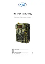
Tour mode settings (TOUR)
1
Setting a new tour mode
Select “TOUR”, and then tilt the joystick
lever to
c
.
The tour setting screen will be displayed.
2
Setting a tour mode number
1
Select “TOUR No.”, and then tilt the joystick lever
to
c
.
The “TOUR No.” setting will flash.
2
Tilt the joystick lever to
j
or
l
to set the number,
and then tilt it to
d
.
Available settings: 001–004
3
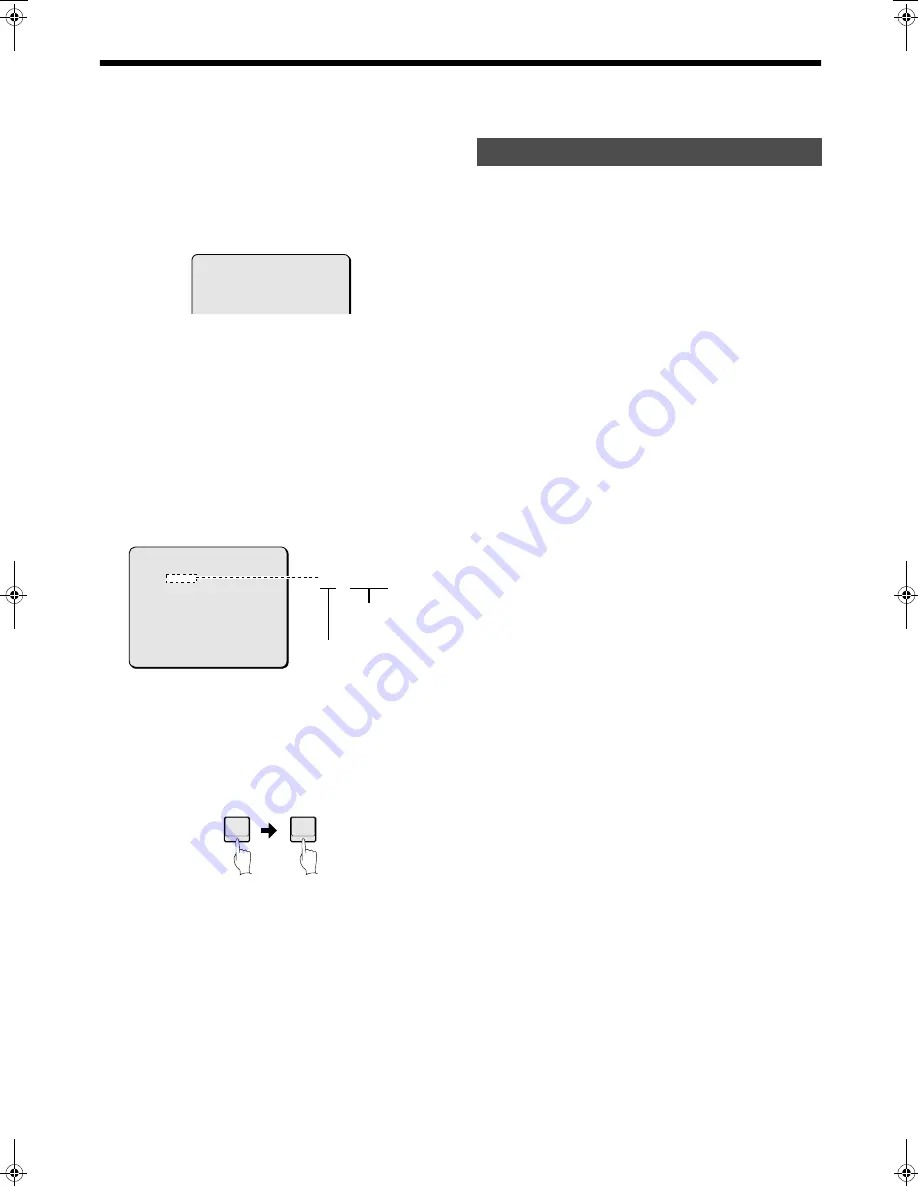
Storing a tour
1
Select “TRACE”, and then tilt the joystick lever to
c
.
The tour recording screen will be displayed.
2
This lets you record zoom operations made by the
joystick lever.
Up to a maximum of 1000 commands can be stored.
3
To stop recording, press the 1 button and then the
ENTER button.
If the recording area is full, recording will stop
automatically.
4
Select “BACK”, and then tilt the joystick
lever to
c
to complete the setting.
1
Select “TOUR”, and then tilt the joystick
lever to
c
.
The tour mode setting screen will be displayed.
2
Select “TOUR No.”, and then tilt the
joystick lever to
c
.
The “TOUR No.” setting will flash.
3
Tilt the joystick lever to
j
or
l
to select a
tour mode number to be checked or
started, and then tilt it to
d
.
4
Checking a tour mode
Tilt the joystick lever to
j
or
l
to select
“SHOW”, and then tilt it to
c
.
Tour mode will be carried out once, and then the display
will return to the menu screen.
5
Starting a tour mode
Select “RUN”, and then tilt the joystick
lever to
c
.
The tour mode will start.
To stop the tour mode, use the joystick lever of the
system controller.
NOTE:
• Recording of a tour mode will start once the first operation
is carried out.
• You can also start the tour mode using the TOUR and +
buttons of the system controller.
• Once 1000 commands have been recorded, the preset
screen will be exited automatically.
6
Select “BACK”, and then tilt the joystick
lever to
c
to complete the setting.
·TOUR No. : 001
TRACE
SHOW
RUN
BACK
CALL PRESET 1 TO
CONFIRM......
0/100
TRACE......
0/100
Usage amount for
stored command
Total percentage
ENTER
1
Checking and starting a tour mode
)* ! "#$%&'
Содержание VCC-9000EBCP/EBSP
Страница 48: ......