3
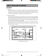
DVD Module
. Summary
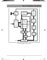
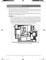
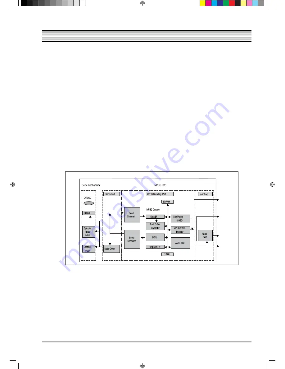
DVD One Board consists of: Loader part that reads and transmits audio and video data saved
at Optic Discs (DVD, CD-DA, VCD, CD-R) to MPEG Decoder part; MPEG Decoder part, which,
by decoding and encoding data received from the Loader, produces analog signals; and u-Com
that controls the overall system including the loader and MPEG decoder.
2. How Does it Operate
Insert the power cord and then power transmitted to each IC, and the SET will be the STAND-
BY status which requires the least power for input the front panel key, input the STAND BY/
ON key, extinguished the LED. Once the Power On key is entered, u-Com recognizes it and
initiates each chipset, performs sequential algorithms such as determining whether the disc
is in or not, and if in, what type of disc is loaded.
Through this process, it can read disc data before transmitting it to the MPEG Decoder. The
MPEG Decoder will then decode and encode such data before generating the final analog
audio and video signal outputs.
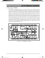
DVD-MODULE Block Diagram
CIRCUIT OPERATIONAL DESCRIPTION
Sm(SANYO_DVD-DX500)051220.indd 3
2005-12-29 8:58:36
Содержание DVD-DX500
Страница 19: ...18 CIRCUIT DIAGRAM 1 POWER SUPPLY SCHEMATIC DIAGRAM Sm SANYO_DVD DX500 051220 indd 18 2005 12 29 8 58 49 ...
Страница 21: ...CIRCUIT DIAGRAM 20 2 RF MPEG SCHEMATIC DIAGRAM Sm SANYO_DVD DX500 051220 indd 20 2005 12 29 8 58 54 ...
Страница 22: ...CIRCUIT DIAGRAM 21 3 SDRAM FLASH SCHEMATIC DIAGRAM Sm SANYO_DVD DX500 051220 indd 21 2005 12 29 8 58 58 ...
Страница 23: ...CIRCUIT DIAGRAM 22 4 VIDEO OUTPUT PORT SCHEMATIC DIAGRAM Sm SANYO_DVD DX500 051220 indd 22 2005 12 29 8 59 01 ...
Страница 24: ...CIRCUIT DIAGRAM 23 5 AUDIO OUTPUT PORT SCHEMATIC DIAGRAM Sm SANYO_DVD DX500 051220 indd 23 2005 12 29 8 59 04 ...
Страница 25: ...CIRCUIT DIAGRAM 24 3 CONTROL BOARD SCHEMATIC DIAGRAM Sm SANYO_DVD DX500 051220 indd 24 2005 12 29 8 59 07 ...


