Service manual
CHASSIS 2112-Series EC7-A
9
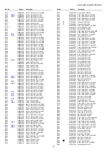
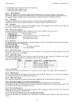
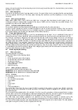
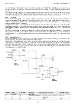
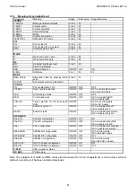
Functionality.
Input (I)
or Output
(O)
Activ
e
Level
Pin
number
(ST92195)
TXT micro
Pin
number
(ST92185)
Not TXT
Related
signal.
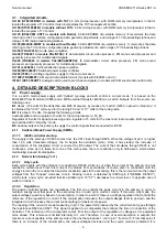
BG system selection
O
L
42
28
CF1
DK system selection
O
L
43
29
CF2
Elimination of AGC feature during
automatic tuning
O
L
44
30
-AGC_LS
LB band selection
O
L
45
31
-LB
MB band selection
O
L
46
32
-MB
Alarm
O
PWM
47
33
BEEP
HB band selection
O
L
48
34
-HB
Width adjust output (optional
circuit)
O
PWM
49
35
WIDTH
Sound mute
O
H
52
38
MUTE
O: Led control
I: Production test communication
I/O
L
53
39
LED
Tuning voltage
O
PWM
54
40
VTUNE
Infrared receptor signal
I
55
41
IR
Keyboard signal
I
A/D
56
42
KEY
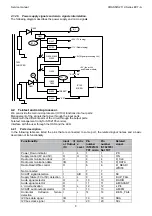
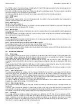
4.2.2 Supply.
The number of supply pins depends on the version (with TXT or without TXT). A list of supply pins is shown in the
attached table, indicating the number and the name of the pin.
Supply pin name
Pin number (Micro with TXT,
ST92195)
Pin number (Micro without
TXT, ST92185)
VDD
21
21
AVDD3
25
---
AVDD2
31
---
AVDD1
39
25
Where:
VDD
!
!
!
!
CPU supply (+5V_M).
AVDD1, AVDD2
!
!
!
!
Analogic supply (+5V_M).
AVDD3
!
!
!
!
Analogic supply (connected internally to AVDD1 and AVDD2).
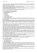
4.2.3 Oscillator.
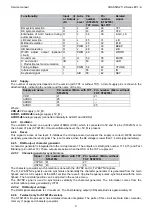
The oscillator is based on a quartz crystal of 8MHz (X100), which is connected to 50 and 51 pins (ST92195) or to
the 36 and 37 pins (ST92185). It must oscillate whenever the +5V_M is present.
4.2.4 Reset.
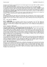
This signal is active at low level. It initialises the microprocessor (whenever the supply is correct). Q858 and his
periphery generate the reset signal. The reset is active when the B2 voltage is lower than 7.4 volts (approximately).
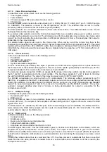
4.2.5
RGB output, character generator.
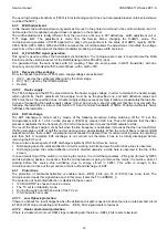
A character generator is integrated into the microprocessor. The outputs are RGB (pins number 17,16,15) and Fast
Blanking (pin number 18). These outputs are active when the OSD or the TXT are present.
4.2.5.1
Character generator synchronism.
Signal
Pin number (Micro with TXT,
ST92195)
Pin number (Micro without
TXT, ST92185)
VSYNC
41
27
HSYNC
40
26
The character generator synchronisation is done with the VSYNC and H_FLY&SYNC signals.
The H_FLY&SYNC signal is used to synchronise horizontally the character generator. It is generated from the main
flyback and it is AC coupled. At the Q651 emitter, there are 8 Vpp line frequency pulses synchronized with the main
flyback. The horizontal position can be adjusted in the service menu.
The VSYNC signal is used to synchronise vertically the character generator. The information comes from the
vertical retrace pulses generated by IC701.
4.2.5.2
RGB output voltage.
The RGB signals amplitude is 1V maximum. The Fast blanking output (VDS) amplitude is approximately 3V.
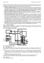
4.2.6
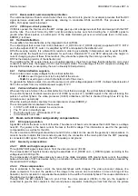
Teletext (only for ST92195 version).
The ST92195 microprocessor has a teletext decoder integrated. The parts of this circuit are Data slicer, decoder,
memory (1 page) and character generator.
Содержание CE14A2-C
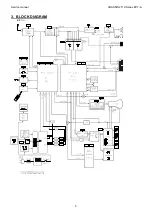
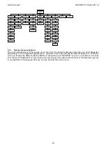
Страница 20: ...Service manual CHASSIS 2112 Series EC7 A 5 3 BLOCK DIAGRAM ...
Страница 48: ......


