Service manual
CHASSIS 2112-Series EC7-A
11
The VTUNE signal is the tuning voltage. Amplifying the 14 bits PWM signal generated by the microprocessor and
low pass filtering generates the tuning voltage.
The –AGC_LS signal is active at low level. It only acts during the autotuning process. The main purpose is avoiding
the AGC actuation in order to discard the weak signals.
The video identification signal and the AFC are read by means of I2C bus from the video processor.
4.2.19 BEEP
signal.
Alarm control.
When the beep signal is active it is a 2 kHz square signal. It is added to the sound amplifier input, being able to
generate a sound similar to the alarm clock one.
4.2.20 WIDTH
signal.
Signal for the width adjustment.
It only acts when Q103 (and periphery) is mounted. This is an optional circuit, it exists as a prevision into the PCB,
but it is possible it does not appear in the schema.
4.2.21 MUTE
signal.
This signal output (that is active at high level) can cancel the sound acting on the audio amplifier input (headphones
and speakers).
The change program mute and the mute from remote control is carried out by the video processor and managed by
the microprocessor using an I2C message.
4.2.22 LED
signal.
It is an output signal that controls de LED intensity; so if it is at low level the light radiated by the led will have more
intensity than when the signal is at high level.
4.2.23 Customer instructions reception (IR and KEY signals).
The customer can act on the TV set via two ways: remote control and TV front keys.
The microprocessor detects when a key is pressed using the KEY signal.
The instructions coming from the remote control are detected by the infrared receiver (RI100) and interpreted by the
microprocessor via the IR signal.
4.3 Horizontal
deflection.
4.3.1 Driver
stage.
The line outputs of video processor (pin 40 of IC400) is a squared signal at line frequency. This signal attacks the
base of Q601, that is configured as transmitter tracker (it does not work in cut / saturation but in active). The output
of base Q601 (transmitter) attacks the base of Q600 by means of C603.
Q600 governs the primary one of T600. In parallel with the primary side of T600 are: C601 and R601, key
components that limit the Q600 collector maximum peak voltage and they also take part in shaping the Q650 base
current.
The secondary side of T600 attacks the Q650 base (). L600 is basic and determines the slope of current extraction
from Q650 base. Its value is defined to cut down the losses of Q650 switching.
T600 is of course a very important component, too. Its construction determines the turn ration as well as a concrete
loss inductance, very low.
4.3.1.1
Driver stage power.
The driver stage supply is the v12V, (by means of R606), that comes from a secondary side from the line
transformer (T650). This secondary side gives a negative flyback. The DC voltage is obtained rectifying this output
by means of D680 and C701. The DC voltage measured by a tester in driver supply is 11,6V, approximately. The
capacitor C600 has been chosen of a small value since it allows a fast transition without problems of 2fh to fh. With
this value, the supply voltage ripple of the driver is 3,5V approximately.
The values of R600 and R606 are fit to correctly determine the Q650 base current. D606 avoids that the vertical
integrated is supplied by B2 voltage, in STAND-BY mode.
4.3.1.2
Driver stage start-up.
Given that when starting the supply of lines does not exist, the start-up of the driver stage, in principle it would not
be possible.
In order to make possible the starting, an initial supply is given, which comes from B2. When the line stage starts
working D600 is conducting, giving a current supplied from B2 (limited by R600) and feeding the driver stage. Once
the voltages of the FBT secondary outputs achieve their final value, D600 will be cut off.
4.3.2 Line
stage.
It is a stage with diode modulator similar to the used one in deflection of 110º. This circuit, composed by C651,
C656, D661 and D662, it allows to compensate the variations of image width when it varies the current in the tube
(effect ' breathing'). As well, it allows cut down the oscillations produced in the deflection when there is a bright
horizontal line and when in the following lines have some information with little luminosity (‘mouse-teeth’ effect).
C653 the ‘S’ correction capacitor and L652 is the linearity coil.
Содержание CE14A2-C
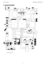
Страница 20: ...Service manual CHASSIS 2112 Series EC7 A 5 3 BLOCK DIAGRAM ...
Страница 48: ......


