Service manual
CHASSIS 2112-Series EC7-A
8
4.1.4.5
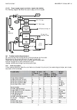
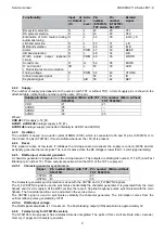
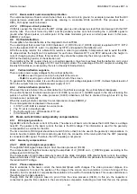
Power supply signals and micro signals interrelation.
The following diagram describes the power supply and micro signals.
Q859, Q860
Q853
IC850
7805
"-SUP_FAIL"
+33V (TV tuning)
+11V (Radio tuning)
Q858
"-RESET"
B2
+5V_M
Q855
"-PD"
Q851
B1_L
R257
R1153
"ON"
B1
+8V (Signal processing Vcc)
IC100
MICRO
T800
CHOPPER
Q856
D850
D851
+5V (tuner Vcc
and Radio module)
4.2
Teletext and microprocessor.
We can divide the main microprocessor (IC100) functions into four parts:
Management of the signals that arrive through the input ports.
Interact with the different parts of the circuit through the output ports.
Teletext management (only for ST92195 version).
Interface with the user through the OSD and the LED.
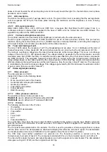
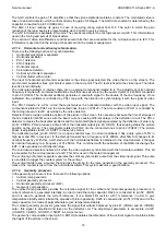
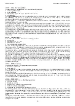
4.2.1 Ports
description.
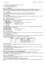
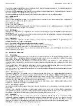
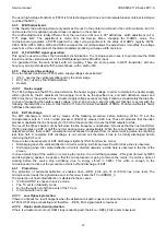
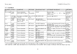
In the following table are listed the pins that are connected to some port, the related signal names and a basic
description of its functionality.
Functionality.
Input (I)
or Output
(O)
Activ
e
Level
Pin
number
(ST92195)
TXT micro
Pin
number
(ST92185)
Not TXT
Related
signal.
Power_Down indicator
I
L
1
1
-PD
Supply control (8V and 5V)
O
H
3
3
ON
Radio communication clock
O
4
4
R_CLK
Radio communication data
I/O
5
5
R_DATA
Radio Read/Write control
O
6
6
-R_READ/
WRITE
Not connected
-
-
7
7
-
SCART signal detection
I
A/D
8
8
SC
Supply failure (8V or 5V) detection
I
L
9
9
-SUP_FAIL
Audio signal selector
O
L
10
10
-RADIO
Audio signal selector
O
11
11
-AM/SCART
L’ circuit activation
O
L
12
12
-LP/L
SCART audio output selector
O
13
13
-AM/FM
Horizontal deflexion failure
detection
I
L
14
14
-DEFL_FAIL
I2C bus data signal
I/O
19
19
SDA
I2C bus clock signal
O
20
20
SCL
Содержание CE14A2-C
Страница 20: ...Service manual CHASSIS 2112 Series EC7 A 5 3 BLOCK DIAGRAM ...
Страница 48: ......

