Service manual
CHASSIS 2112-Series EC7-A
22
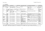
5.2 Adjustments.
ADJUSTME
NT
SIGNAL
CONDITIONS
TEST POINT
ADJUSTMENT POINT
ADJUSTMENT PROCEDURE
INSTRUMEN
T
Power supply Philips
pattern
Picture: Normalised
Sound: Minimum volume
B1
Cathode D850
VR800
Adjust to obtain:
106,5V
±
0.5V in CRTs Philips
A34EAC01X06
Voltmeter DC
Resolution
>0,1V
A.G.C.
UHF Band –
mid channel
(e.g. 25)
Aerial signal level: 60dBuV
(1mVrms)
Pin 1 of TU250
(AGC)
SERVICE/VIF/AGC
Adjust to obtain 3,0
±
0,5V
Voltmeter DC
Resolution
>0,1V
G2
Philips
pattern
SERVICE/G2/BRI:
50 for Philips CRT
A34EAC01X06
CRT Screen
SERVICE/G2/ADJ
SCREEN Potentiometer
Adjust just to see the service line
Visual
adjustment
Focus
Philips
pattern
Picture: Normalised
CRT Screen
FOCUS Potentiometer
Adjust to obtain the best possible focusing in
lateral of screen.
Visual
adjustment
Vertical slope Philips
pattern
Picture: Normalised
CRT Screen
SERVICE/GEOMET>/V.SL
OPE
Adjust to achieve that the centre horizontal
line matches the beginning of the service
blanking.
Visual
adjustment
Vertical
centre
Philips
pattern
Picture: Normalised
CRT Screen
SERVICE/GEOMET>/V.S
HIFT
Adjust to centre the picture in vertical
direction
Visual
adjustment
Height
Philips
pattern
Picture: Normalised
CRT Screen
SERVICE/
GEOMET>/V.AMPL
Adjust just to get the checked board hidden.
Visual
adjustment
Horizontal
centre
Philips
pattern
Picture: Normalised
CRT Screen
SERVICE/
GEOMET>/H.SHIFT
Adjust to centre the picture in horizontal
direction.
Visual
adjustment
Width
Philips
pattern
Picture: Normalised
CRT Screen
SERVICE/
GEOMET>/H.AMPL
Adjust just to get the checked board hidden.
Visual
adjustment
White point
Philips
pattern
Picture: Normalised
CRT Screen
SERVICE/WHITE/G
SERVICE/WHITE/B
Adjust to obtain a white tone acceptable.
Visual
adjustment
TXT centre
Philips
pattern
Picture: Normalised
CRT Screen
SERVICE/GEOMETCENT
R TXT
Adjust to centre the OSD in the screen.
Visual
adjustment
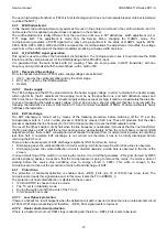
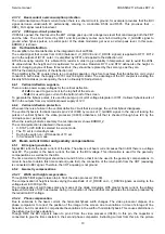
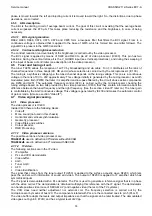
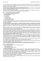
Common condition to all adjustments (except AGC): The aerial signal level must be acceptable (the picture doesn’t present snow degradation).
Width adjustment, H.AMPL, lacks effect whenever the circuit of adjustment is not mounted, which is optional, according to it has been indicated previously.
Содержание CE14A2-C
Страница 20: ...Service manual CHASSIS 2112 Series EC7 A 5 3 BLOCK DIAGRAM ...
Страница 48: ......

