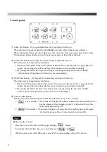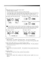
2.
In2 (Input test 2)
・
After 1.2 process, when
is displayed, push
④
Enter button.
・
When
⑤
Set/Select Dial is turned, input display number registered in software
(Table -1) is displayed by turns. The lamp of
③
Short button will be turned on if displayed
input sensor is in ON setting.
3.
out
(
output test
)
・
After 1,2 process, when
is displayed, push
④
Enter button.
・
Select display number of
(
table- 2
)
with
⑤
Set/Select Dial. When
④
Enter button is
pushed, test operation starts.
Table
-
2
Output test list
Display
number
Output name
Notes
2
A
Close Middle Arm
Valve
①
2
b
Close Upper Press Arm
Valve
②
2
c
Close Upper Press
Valve
③
4.
VoL
(
Volume function setting
)
・
After 1, 2 process, when
is displayed, push
④
Enter button.
・
After display number (table3) is selected with
⑤
Set/Select Dial, when
④
Enter button is
pushed, present setting time is displayed. Setting time is changed with
⑤
Set/Select Dial and
push
④
Enter button to save it.
Table
-
3
Volume list
Display
number
Setting contents
Factory setting time
V 1
Time from cuff press move to until down.
1.8sec.
(
Max.3.0 sec.
)
V 2
Time between collar press head rising and collar press arm,
cuff press arm rising.
0.0sec.
(
Max.1.0 sec.
)
V 3
Time between cuff press operation and starting of collar /cuff
mode.
1.0sec.
(
Max.10.0 sec.
)
V 4
Time between collar press head finishing and collar mode
starting.
1.0sec. (Max.10.0 sec.
)
V 5
Time between collar press head rising and cuff press rising.
0.5sec.
(
Max.1.0 sec.
)
An output test should stop air and steam.
There is possibility of machine failure or burn.
CAUTION
25
Содержание LP-660E-V2
Страница 2: ......
Страница 38: ...36...
Страница 39: ...Spare Parts List Index 1 Front Diagram 2 Rear Diagram 3 Steam Piping 4 Cover Diagram 37...
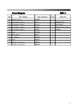
Страница 40: ...1 Front Diagram REV 1 38...
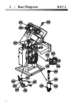
Страница 42: ...2 Rear Diagram REV 1 201 202 207 203 204 205 205 206 208 209 210 211 212 213 214 215 216 217 218 40...
Страница 44: ...3 Steam Piping REV 1 42...
Страница 46: ...4 Cover Diagram REV 1 44...
Страница 48: ...Diagram Sensor Diagram Electric Connection Diagram 1 4 4 4 Steam Piping Diagram All Air System 46...
Страница 50: ......
Страница 51: ......
Страница 52: ......
Страница 53: ......


