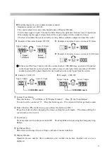
About the display of cover counter and press counter
Maximum counter is 9,999,999.
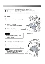
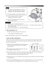
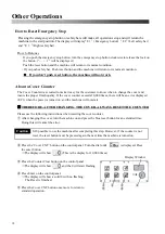
The counter shows twice due to the limited space of Display Window.
First it shows upper 3 digits. Turn the Set/Select Dial to the right next. It shows lower 3 digits next.
When displaying the upper 3 digits, there will be a period placed in the window to denote
which set of numbers the user is currently viewing. Below contains a diagram of how this works.
◎
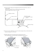
In the case of the Press Counter, when the counter reaches 1,000,000 times, a period will be placed
in the Upper Number section, beside the number closest to the right. After exceeding 2,000,000,
another period will be placed beside the next number in line in the Upper Number section.
⑤
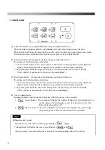
Counter Clear Button
Press this button. "0" will blink at
⑨
"Display Window". Press
⑥
the "Enter Button".
You can reset the counter at "0". Press this button again. The window will show garment counter.
⑥
Enter Button (The light turns green when the button is ON.)
Press this button after changing the timer setting for each mode. The time setting for
each mode can be saved.
⑦
Power Lamp
The lamp turns red when the power turns ON. The lamp blinks when pressing the Emergency Stop
Button.
⑧
Set/Select Dial
This dial can change timer settings and select menu numbers.
⑨
Display Window.
Operation process number, timer countdown, error number, menu item (number) and so on are
displayed.
Upper 3 digits
Lower 3 digits
Example of Maximum Counter
(
999,999
)
Example of a display in case a counter is 999 times
Example of a display in case a counter is 12,000 times
Upper
Period
Lower
Period
Upper 3 digits
Lower 3 digits
Example : 1,001,999
1,000,000th mark
Upper 3 digits
Lower 3 digits
Example : 2,009,999
2,000,000th mark
13
Содержание LP-660E-V2
Страница 2: ......
Страница 38: ...36...
Страница 39: ...Spare Parts List Index 1 Front Diagram 2 Rear Diagram 3 Steam Piping 4 Cover Diagram 37...
Страница 40: ...1 Front Diagram REV 1 38...
Страница 42: ...2 Rear Diagram REV 1 201 202 207 203 204 205 205 206 208 209 210 211 212 213 214 215 216 217 218 40...
Страница 44: ...3 Steam Piping REV 1 42...
Страница 46: ...4 Cover Diagram REV 1 44...
Страница 48: ...Diagram Sensor Diagram Electric Connection Diagram 1 4 4 4 Steam Piping Diagram All Air System 46...
Страница 50: ......
Страница 51: ......
Страница 52: ......
Страница 53: ......

