background image

23

EN

3.2. AT START UP

•  Before you handle this equipment, ensure it is disconnected from the mains power supply.
•  Check that the mains voltage and frequency are the same as specifi ed on the name plate.
•  Follow the wiring diagram to make the electrical connections. 
•  Check that the earthing, if any, is correct and that the thermal and surge protection has been 

connected and are within the relevant limits.

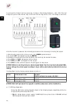
4. COMMISSIONING OF PLUG & PLAY MODES FROM THE FACTORY 

VFTM320 drives come pre-programmed by S&P. For this, it is necessary to make a bridge between 
DI3 - R2C and another between DI4-R2A and, in this way, two 

plug & play 

operating modes are 

obtained following corresponding wiring diagrams:

1. Manual control mode

 through integrated frontal Wheel (check 4.1 paragraph) 

2. Constant pressure (COP) mode 

(PI control) with 0-10V analog signal input (check 4.2 paragraph)

ATTENTION: Check SW1 micro switch is positioned to the right and SW2 to the left

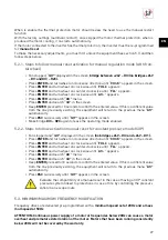
Navigation through the menus of the frequency drive will be carried out using the commands de-
scribed below:

= ENTER

= BACK

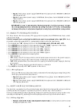
4.1. MANUAL CONTROL WITH INTEGRATED FRONTAL WHEEL 

With this confi guration, the user will be able to modify the speed of the fan as well as the stop / start 
of the equipment through the front potentiometer.

Содержание VFTM 320 IP20

Страница 1: ...VFTM 320 IP20 IP66 ES EN FR...

Страница 2: ......

Страница 3: ...tecci n t rmica del motor parada emergencia 11 5 4 1 Esquema de conexiones 11 5 5 Habilitar protecci n t rmica PTC 12 5 5 1 Esquema de conexiones 12 5 6 Realizar funci n Paro Marcha mediante interrupt...

Страница 4: ...ado para soportar las condiciones normales de trans porte no se debe transportar el aparato fuera de su embalaje original ya que podr a deformarse o deteriorarse El almacenaje del producto debe reali...

Страница 5: ...ncia de la red de alimentaci n son iguales a los indicados en la placa de caracter sticas Para la conexi n el ctrica siga las indicaciones de los esquemas de conexi n al nal del manual Comprobar que l...

Страница 6: ...est activo el puente 24V DI1 Una vez alimentado el variador para modi car la velocidad ser necesario el siguiente procedi miento 1 Viendo en pantalla la velocidad en Hz pulsar ENTER potenci metro 2 E...

Страница 7: ...4 2 MODO PRESI N CONSTANTE COP CONTROL PI Este modo de funcionamiento se utiliza para garantizar un determinado valor de sobrepresi n en un recinto respecto a otro Ejemplos de esta aplicaci n sobrepr...

Страница 8: ...30 400V o 400V sin protector t rmico y se al 0 10V rearme autom tico El variador de frecuencia se pondr en marcha autom ticamente al recibir ten si n de alimentaci n y realizar las funciones de contro...

Страница 9: ...ma sucesiva hasta que rdY aparezca en pantalla 5 2 REARME MANUAL REARME AUTOM TICO Los convertidores de frecuencia se entregan pre programados con rearme autom tico Esto signi ca que en caso de corte...

Страница 10: ...do negativo hasta que aparezca FLt en pantalla Pulsar ENTER y girar la rueda en sentido positivo hasta que aparezca Atr en pantalla Pulsar ENTER y buscar men Atr en pantalla Pulsar ENTER y buscar nO e...

Страница 11: ...arado y rdY en pantalla sin puentes 24V DI3 ni 24V DI1 Pulsar ENTER y girar la rueda en sentido positivo hasta que aparezca COnF en pantalla Pulsar ENTER y girar la rueda en sentido positivo hasta que...

Страница 12: ...ilitado A5 Siempre La sonda PTC realiza la supervisi n de forma ininterrumpida aunque la ali mentaci n el ctrica no est conectada siempre que el control permanezca conectado a la alimentaci n el ctric...

Страница 13: ...talla Pulsar ENTER y girar la rueda en sentido positivo hasta que aparezca LSP en pantalla Pulsar ENTER y girar la rueda hasta que aparezca 20 en pantalla Pulsar ENTER para con rmar el valor introduci...

Страница 14: ...protector t rmico Fig 4 2 Alimentaci n trif sica 3 400 50 60 motor trif sico 230 400V o 400V sin protector t rmico Fig 4 3 Alimentaci n monof sica 1 230 50 60 motor trif sico 230 400V con protector t...

Страница 15: ...sucesiva hasta que FULL aparezca en pantalla 3 Relaci n velocidad m nima LSP y m xima HSP con se al 4 20mA Ventilador parado y FULL en pantalla sin puentes 24V DI3 ni 24V DI1 Pulsar ENTER y girar la...

Страница 16: ...I3 ni 24V DI1 Pulsar ENTER y girar la rueda en sentido positivo hasta que aparezca COnF en pantalla Pulsar ENTER y girar la rueda en sentido positivo hasta que aparezca FULL en pantalla Pulsar ENTER y...

Страница 17: ...e presi n a mantener La consigna a mantener depender del par metro rPI que es un par metro con gurable entre 0 1000 Ejemplos Rango sonda Valor rPI introducido Consigna de presi n a mantener por VFTM32...

Страница 18: ...s compuertas de regulaci n de caudal existentes En casos ser necesario mantener una presi n constante en la red de conductos y la consigna de presi n se deber determinar de forma experimental durante...

Страница 19: ...imentaci n trif sica 3 400 50 60 motor trif sico 230 400V o 400V sin protec tor t rmico y se al 0 10V rearme autom tico Fig 2 3 Alimentaci n monof sica 1 230 50 60 motor trif sico 230 400V con protect...

Страница 20: ...rsonal cuali cado y en cumplimiento de las normas locales e internacionales Desconectar el equipo el ctrico de la red de alimentaci n asegur ndose que nadie pueda ponerlo en marcha durante la operaci...

Страница 21: ...modi cation 27 5 4 Enable motor thermal protection emergency stop 28 5 4 1 Wiring diagram 28 5 5 Enable ptc thermal protection 29 5 5 1 Wiring diagram 29 5 6 On off control by external switch 29 5 6...

Страница 22: ...hows signs of having been tampered with Prevent the packaging from falling and being knocked and do not place heavy loads on it 3 SAFETY RULES 3 1 ON INSTALLATION Installation and commissioning must b...

Страница 23: ...e a bridge between DI3 R2C and another between DI4 R2A and in this way two plug play operating modes are obtained following corresponding wiring diagrams 1 Manual control mode through integrated front...

Страница 24: ...and the selected speed in Hz will appear on the screen ATTENTION Even selecting in step 3 a desired speed higher than the maximum allowable 50Hz factory setting the actual speed resulting in step 6 w...

Страница 25: ...0 100Pa the system will seek to maintain a value of 50 Pa in the over pressured chamber Before starting the system check this point For systems where it is necessary to modify the set point associated...

Страница 26: ...he following sequence Fan stopped and rdY displayed in the screen no bridges 24V DI3 and 24V DI1 Press ENTER and turn wheel on clock wise direction until Non appears in the screen Press ENTER and turn...

Страница 27: ...uccessively until rdY appears in the screen Make bridge DI3 R2C again to leave the operating mode enabled 5 2 2 Steps to follow activation manual reset for constant pressure mode COP Fan stopped and r...

Страница 28: ...d front potentiome ter In case of manual regulation the potentiometer must be remote see section 5 7 Procedure to enable motor thermal protection bimetal type to stop the frequency drive in case of mo...

Страница 29: ...e until PtC appears Press ENTER and turn wheel on clock wise until PtCL appears Press ENTER on desired function knowing that no Disabled A5 Always The PTC probe performs uninterrupted supervision even...

Страница 30: ...LSP appears Press ENTER and turn wheel until 20 appears Press ENTER to con rm value selected If this is a different value from the one previously exist ing the equipment will return to the previous me...

Страница 31: ...phase motor 230 400V o 400V with out thermal protection Fig 4 3 Single phase power supply 1 230 50 60 three phase motor 230 400V with ther mal protection IMPORTANT Before wiring read points 5 2 and 5...

Страница 32: ...o bridges 24V DI3 and 24V DI1 Press ENTER and turn wheel on clock wise direction until I_O appears in the screen Press ENTER and turn wheel on clock wise until AI3 appears Press ENTER and turn wheel o...

Страница 33: ...Press ENTER and turn wheel on clock wise direction until COnF appears in the screen Press ENTER and turn wheel on clock wise until FULL appears Press ENTER and turn wheel on clock wise until FUn appe...

Страница 34: ...the constant pressure system is around 2 times the pressure set point to maintain The set point to maintain will depend on the rPI parameter which is a con gurable parameter between 0 1000 Examples S...

Страница 35: ...sed In both cases the pressure must be constant in the duct system The value of this pressure must be determined by experimenting during the system start up process For this adjustment it is essen tia...

Страница 36: ...y 3 400 50 60 three phase motor 230 400V o 400V without thermal protection and 0 10C signal automatic reset Fig 2 3 Single phase power supply 1 230 50 60 three phase motor 230 400V with ther mal prote...

Страница 37: ...personnel and in compliance with local and international regulations Disconnect the electrical equipment from the power supply making sure that no one can start it during the operation Disassemble an...

Страница 38: ...4 Activer protection thermique du moteur arret d urgence 45 5 4 1 Sch ma de c blage 46 5 5 Activer une protection thermique PTC 46 5 5 1 Sch ma de c blage 47 5 6 Realiser la fonction marche arret au...

Страница 39: ...tout dommage ou d formation Le produit doit tre stock dans son emballage d origine dans un endroit sec et l abri de la salet jusqu son installation nale N accepter aucun appareil qui ne soit pas livr...

Страница 40: ...s indiqu es sur la plaque signal tique Pour le raccordement lectrique se reporter aux sch mas de raccordement situ s la n du manuel S assurer que la mise la terre a t effectu e correctement et que les...

Страница 41: ...tiom tre jusqu obtenir la valeur en Hz souhait e 4 Appuyer sur ESC et le message AIUI s af che l cran 5 Appuyer sur ESC et le message rEF s af che l cran 6 Appuyer sur ESC et la vitesse s lectionn e e...

Страница 42: ...sortie analogique 0 10V et plages d chelle param trables S P mod le 5416731400 TDP D ATTENTION Par d faut le param trage de la commande PI a comme valeur de consigne la pres sion associ e 5V du signa...

Страница 43: ...aphe 4 il est n ce ssaire de recon gurer manuellement certains param tres du convertisseur de fr quence Pour ce faire tenir compte de la navigation dans les menus suivants de l appareil ENTER RETOUR V...

Страница 44: ...suivre pour activer le r armement manuel pour mode de r gulation manuelle avec potentiom tre int gr Ventilateur arr t rdY s af che l cran pontage 24V DI3 actif sans pontages 24V DI1 ni DI3 R2C Appuyer...

Страница 45: ...u convertisseur en cas de portes ferm es pour viter de d passer la valeur de surpression x e par la r glementation en vigueur Pour ce faire il faut d verrouiller le convertisseur paragraphe 5 1 puis m...

Страница 46: ...reprend sa position initiale ferm e le convertisseur ne red marre pas tant que la tension n a pas t coup e et que le courant r tabli r armement manuel L installateur utilisateur ne doit pas red marre...

Страница 47: ...e PTC Fig 1 4 Alimentation triphas e 3 400 50 60 moteur triphas 230 400V ou 400V avec pro tection thermique PTC 5 6 REALISER LA FONCTION MARCHE ARRET AU MOYEN DE L INTERRUPTEUR EXTERNE Cette fonction...

Страница 48: ...rdY s af che de nouveau l cran Une fois ce param trage effectu le convertisseur fonctionne en proportionnel un signal externe de 0 10V Avec 0V le ventilateur tourne la fr quence minimale 20 Hz Avec 10...

Страница 49: ...on du terminal NC Fig 4 4 Alimentation triphas e 3 400 50 60 moteur triphas 230 400V ou 400V avec pro tection thermique IMPORTANT avant de proc der au c blage lire les points 5 2 et 5 4 pour d termine...

Страница 50: ...pport vitesse minimum LSP et maximum HSP avec signal 4 20mA Ventilateur arr t et FULL l cran sans pontages 24V DI3 ni 24V DI1 Appuyer sur ENTER et faire tourner la roue dans le sens positif jusqu ce q...

Страница 51: ...IS VITESSES PR S LECTIONN ES Cette fonction permet de disposer de trois vitesses pr s lectionn es au moyen de signaux num riques contacts libres de potentiel Pour r aliser les r glages n cessaires il...

Страница 52: ...4V DI1 10V AI1 Vitesse tape 3 HSP 50Hz Modif vitesse maximum paragraphe 5 3 5 10 1 Sch ma de c blage R aliser le sch ma de c blage convertisseur moteur indiqu dans les gures suivantes selon le type de...

Страница 53: ...C CAPTEUR ANALOGIQUE EXTERNE ET SIGNAL 0 10V Ce param trage permet d obtenir la fois un mode de d bit constant CAV et un mode de pression constante COP D bit constant CAV Le convertisseur est utilis p...

Страница 54: ...tallation SONDE DE PRESSION CONVERTISSEUR DE FREQUENCE VENTILATEUR FILTRE Sch ma d installation D bit constant CAV SONDE DE PRESSION CONVERTISSEUR DE FREQUENCE VENTILATEUR REGISTRES MOTORIS S Sch ma d...

Страница 55: ...SOURCE R aliser les pontages indiqu s sur le bornier du convertisseur Alimenter le convertisseur de fr quence avec la tension d alimentation appropri e en fonction du mod le de convertisseur utilis L...

Страница 56: ...I3 COM AQ1 R1A R1B R1C R2A R2C SRC PLC SINK LI6 PTC M 3 L N 1 230V 50 60Hz 3 230 400V 50Hz R L1 S N U T1 V T2 W T3 RJ45 DQ DQ PE 24 DI1 DI2 DI3 DI4 DI5 DI6 STO P24 10V AI1 COM AI2 AI3 COM AQ1 R1A R1B...

Страница 57: ...Q1 R1A R1B R1C R2A R2C SRC PLC SINK LI6 PTC M 3 L N 1 230V 50 60Hz 3 230 400V 50Hz PTC PTC R L1 S N U T1 V T2 W T3 M 3 L1 L2 3 400V 50 60Hz 3 400V 50Hz 3 230 400V 50Hz 3 400 690V 50Hz R L1 L3 RJ45 DQ...

Страница 58: ...R2C SRC PLC SINK LI6 PTC M 3 L N 1 230V 50 60Hz 3 230 400V 50Hz 1 2 3 4 SW2 SW1 0 10V GND 24V R L1 S N U T1 V T2 W T3 RJ45 DQ DQ PE 24 DI1 DI2 DI3 DI4 DI5 DI6 STO P24 10V AI1 COM AI2 AI3 COM AQ1 R1A...

Страница 59: ...LC SINK LI6 PTC M 3 L N 1 230V 50 60Hz 3 230 400V 50Hz 1 2 3 4 SW2 SW1 0 10V GND 24V TP TP R L1 S N U T1 V T2 W T3 M 3 L1 L2 3 400V 50 60Hz 3 400V 50Hz 3 230 400V 50Hz 3 400 690V 50Hz R L1 L3 1 2 3 4...

Страница 60: ...6 PTC M 3 L N 1 230V 50 60Hz 3 230 400V 50Hz SW2 SW1 0 10V GND 24V 5 4 3 2 1 10V C REB ECOWATT R L1 S N U T1 V T2 W T3 RJ45 DQ DQ PE 24 DI1 DI2 DI3 DI4 DI5 DI6 STO P24 10V AI1 COM AI2 AI3 COM AQ1 R1A...

Страница 61: ...M 3 L N 1 230V 50 60Hz 3 230 400V 50Hz SW2 SW1 0 10V GND 24V 5 4 3 2 1 10V C REB ECOWATT TP TP R L1 S N U T1 V T2 W T3 RJ45 DQ DQ PE 24 DI1 DI2 DI3 DI4 DI5 DI6 STO P24 10V AI1 COM AI2 AI3 COM AQ1 R1A...

Страница 62: ...400V 50Hz SW2 SW1 0 10V AIRSENS N L NO COM NC OUT 0V SW 1 2 3 4 ON SW 1 ON 0 10V GND R L1 S N U T1 V T2 W T3 RJ45 DQ DQ PE 24 DI1 DI2 DI3 DI4 DI5 DI6 STO P24 10V AI1 COM AI2 AI3 COM AQ1 R1A R1B R1C R2...

Страница 63: ...SW2 SW1 0 10V AIRSENS N L NO COM NC OUT 0V SW 1 2 3 4 ON SW 1 ON 0 10V GND TP TP R L1 S N U T1 V T2 W T3 L1 L2 3 400V 50 60Hz 3 400V 50Hz 3 230 400V 50Hz 3 400 690V 50Hz R L1 L3 0 10V AIRSENS N L NO C...

Страница 64: ...3 L N 1 230V 50 60Hz 3 230 400V 50Hz SW2 SW1 4 20mA SCO2 AD SCHT AD GND RH Gnd V T Gnd CO 24V R L1 S N U T1 V T2 W T3 RJ45 DQ DQ PE 24 DI1 DI2 DI3 DI4 DI5 DI6 STO P24 10V AI1 COM AI2 AI3 COM AQ1 R1A...

Страница 65: ...30V 50 60Hz 3 230 400V 50Hz SW2 SW1 4 20mA SCO2 AD SCHT AD GND RH Gnd V T Gnd CO 24V M 3 TP TP R L1 S N U T1 V T2 W T3 RJ45 DQ DQ PE 24 DI1 DI2 DI3 DI4 DI5 DI6 STO P24 10V AI1 COM AI2 AI3 COM AQ1 R1A...

Страница 66: ...3 230 400V 50Hz ON OFF V1 V2 V3 ON OFF 24 DI1 V1 24 DI1 V2 24 DI1 24 DI2 V3 24 DI1 10V AI1 R L1 S N U T1 V T2 W T3 RJ45 DQ DQ PE 24 DI1 DI2 DI3 DI4 DI5 DI6 STO P24 10V AI1 COM AI2 AI3 COM AQ1 R1A R1B...

Страница 67: ......

Страница 68: ...S P SISTEMAS DE VENTILACI N S L U C Llevant 4 Pol gono Industrial Llevant 08150 Parets del Vall s Barcelona Espa a Tel 34 93 571 93 00 www solerpalau com Ref 1441416 3...

Отзывы: