background image

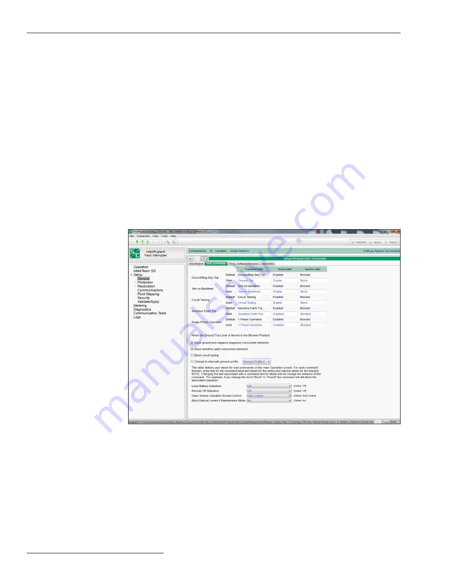
Figure 13. The 

Setup>General>User Commands

 screen.

The 

Operation

 screen has five commonly used functions that accommodate customized 

labeling. See Figure 13. The text for those custom labels is configured in the 

Command 

Label

Active Label

, and 

Inactive Label

 fields found on the 

Setup>General>User 

Commands

 screen.

User Commands

Note: 

Changing the text associated with a command and its labels will not change the 

behavior of the command. For example, if you change the word “Block” to “Permit,” the 
command will still block the associated operation.

Maximum Interrupting Current

Options are 12.5 kA and 16 kA. The 12.5-kA setting is available for all system voltages and 
the 16-kA setting may only be used for system voltage up to 15.5 kV. There is a validation 
rule that prevents a 16-kA selection for higher voltages. Tripping is blocked when current 
is above the 

Maximum Interrupting Current

 setting.

Use Least-Used Poles First in Closing Profiles

When set to the 

Yes

 option, the pole with the highest 

Remaining Contact Wear

 value 

will close first when using either 

Closing Profile

 setting. Otherwise, the closing sequence 

will be Pole 1, followed by Pole 2, and then Pole 3. Default is the 

No

 option.

Frequency Difference Threshold

This setting is used by the 

Metering>Sync Check

 screen. When the absolute value of 

the difference in frequency between Terminal X and Terminal Y exceeds this threshold, 
the frequency values are displayed in red. (Range: 0.1-5.0; Step: 0.1; Default: Disabled)

26    S&C Instruction Sheet 766-530

General Setup

Содержание IntelliRupter PulseCloser

Страница 1: ...lt 37 CEC Example for a Complex Network 38 Protection Setup Initial Trip Settings Direction 1 39 TCCs for Test Sequence 62 TCCs for Coordination 67 Direction 2 Configuration 72 Testing After Initial Trip 73 Voltage Trip 78 Frequency Trip 83 Sectionalizing Trip 86 Hot Line Tag 88 Closing Profile 98 Closing Profile 2 Configuration 109 Cold Load Pickup 109 Advanced Setup 111 Loop Restoration Profile ...

Страница 2: ...rate and maintain the equipment covered by this publication A qualified person is someone who is trained and competent in The skills and techniques necessary to distinguish exposed live parts from nonlive parts of electrical equipment The skills and techniques necessary to determine the proper approach distances corresponding to the voltages to which the qualified person will be exposed The proper...

Страница 3: ...edy shall be additional system analysis and reconfiguration of the IntelliTeam SG Automatic Restoration System until the desired result is achieved Warranty of the IntelliRupter fault interrupter is contingent upon the installa tion configuration and use of the control or software in accordance with S C s applicable instruction sheets This warranty does not apply to major components not of S C man...

Страница 4: ...cautions are not followed NOTICE NOTICE identifies important procedures or requirements that can result in product or property damage if instructions are not followed If you do not understand any portion of this instruction sheet and need assistance contact your nearest S C Sales Office or S C Authorized Distributor Their telephone numbers are listed on S C s website sandc com or call the S C Glob...

Страница 5: ... integrated power module IPM contains components that can retain a voltage charge for many days after the IntelliRupter fault interrupter has been de energized and can derive a static charge when in close proximity to a high voltage source Voltage levels can be as high as the peak line to ground voltage last applied to the unit Units that have been energized or installed near energized lines shoul...

Страница 6: ...lted line segments by closing the IntelliRupter fault interrupter at the normally open switching point The automatic source transfer system uses two IntelliRupter fault interrupters with peer to peer communication to ensure a high degree of critical load continuity by minimizing interruptions resulting from the loss of one source The IntelliTeam SG system monitors real time load and it uses peer t...

Страница 7: ... any test after the initial fault trip The hard close may be required to allow a fuse operation after the initial fuse saving operation Up to four test operations can be configured and each can be a PulseClosing Technology operation or a conventional close A different inverse curve can be used for each close Conventional closing subjects the system to high impact fault current at each closing oper...

Страница 8: ...p to lockout Closing Profile operations are time limited and will switch to the assigned general profile when closing is successful A second Closing Profile operation with different parameters than the first Closing Profile operation may be selected Single Phase Trip IntelliRupter fault interrupters can be configured to open only the faulted phases for an overcurrent trip signal Cold Load Pickup T...

Страница 9: ...s only set the External Device Data Updated mode to the Running setting STEP 7 Enable the Automatic Restoration mode on all upgraded controls Coordinaide software can plot various TCC curves for a protection overcurrent element direction The curves appropriate for both the upstream and downstream protective devices can then be selected and their parameters downloaded to a Setpoints Group File for ...

Страница 10: ... screen On the Operation screen Operation is highlighted on the left menu Screens having multiple topics are tabbed as shown in Figure 2 on page 11 When a particular topic is selected the tab is highlighted Clicking on the change buttons next to the user commands found on the lower portion of the Operation screen will toggle the command state The active state is shown by the word displayed on the ...

Страница 11: ...are screens by clicking on the Operation menu item on the navigation tree at the left of the screen The Operation screen contains three message indicators See Figure 1 on page 10 The list of possible messages in the order of precedence is Settings Mismatch LOCKOUT OC LOCKED OPEN LOCKOUT SEF Close Blkd No Energy PICKUP FREQ Fault Pulseclosing PICKUP SECT Lockout Pulseclosing PICKUP VOLTS Close Blkd...

Страница 12: ...s dialog box Zoom In Clicking on this icon increases the size of objects and text in the screen area See Figure 2 on page 11 Zoom Out Clicking on this icon decreases the size of objects and text in the screen area See Figure 2 on page 11 Validate Same as Validate button on the Setup Validate Apply screen See Figure 113 on page 178 Checks the pending changes does not apply them Apply Sa me a s A p ...

Страница 13: ...ield shows the user defined device location The device location is entered on the Setup General Site Related screen Validate Status This field shows the status of the Validate and Apply functions Navigation Tools Navigation History Clicking on this icon opens a list of the last 10 screens visited Selecting a screen from the list will automatically transition from the present screen to the selected...

Страница 14: ... hidden or grey shaded Data fields for disabled items cannot be changed Text Expanders Expanders are provided to help manage the view When the data below the expander is visible the expander icon arrow points up Clicking on the icon collapses or hides the data from view When the data is hidden the expander arrow points down Clicking on the icon displays the hidden date Communication Status The com...

Страница 15: ... by the integrated Global Positioning System is automatically displayed IntelliRupter Base Serial Number The serial number is automatically read from the base memory module IntelliRupter Control Serial Number This serial number is automatically read from the protection and control module Catalog Number The catalog number is automatically read from the base memory module Base Memory Module Version ...

Страница 16: ...ches a critical level because of loss of line power and a low battery charge Opening on loss of control power limits in rush current when the circuit is re energized and feeder segments are sequentially picked up Select the No option to configure the IntelliRupter fault interrupter to remain closed when stored energy is depleted Time Limit for Sleep Do Not Resume Operations This is the maximum num...

Страница 17: ...memory module States are stored for these functions Ground Neg Seq Trip Enable Block Loop Restoration Enable Disable Circuit Testing Enable Block Test on Backfeed Enable Block Sensitive Earth Trip Enable Block Single Phase Trip Enable Block Remote Operation Enable Disable HLT Set by SCADA HLT Set by IntelliLink Latched Overcurrent Execute When the GROUND TRIP manual lever is in the Blocked state i...

Страница 18: ... of their event records must match for events to be considered duplicates This setpoint selects data to be stored in the internal memory and be displayed on the Logs Historic Log screen It determines the time between logging a duplicate event It has no effect on an alternating sequence of events For example the setpoint can be set to 10 ms For a sequence of events ABABAB where A and B are differen...

Страница 19: ...ation is displayed on the Metering screen Until then the Metering screen displays the phase rotation setting on the Setup General System Phase Rotation screen Until terminal X phase rotation is measured the IntelliRupter fault interrupter measures positive and negative sequence voltage based on the 123 or 132 setting in Setup General System Phase Rotation screen In the event the phase rotation set...

Страница 20: ... the Direction 1 Direction 2 configuration is X Y Direction 1 protection settings are applied to a fault that flows into the Y terminal and out of the X terminal See Figures 7 8 and 9 on page 21 The IntelliTeam Automatic Restoration System uses the voltage measured on the terminal configured as Direction 1 to determine the Good Source Voltage measure ment The Direction 1 terminal must be configure...

Страница 21: ...gure 7 Direction 1 Direction 2 XY default Figure 8 Direction 1 Direction 2 YX Figure 9 Set the first letter as the source Direction 2 will always be the load S C Instruction Sheet 766 530 21 General Setup ...

Страница 22: ...Y X column data System Type Select from the drop down list Multi Grounded default Uni Grounded Uni Grounded Solid Uni Grounded Resistive Uni Grounded Reactive or Uni Grounded Resonant The selection affects how the Overcurrent element and SEF element directionality are determined Directional Protection Directional fault determination is made based on the signals available within the specified prote...

Страница 23: ...minal Y Phase A directional measurement as an example VBC is the reference voltage and IA is the operating current The Terminal Y Phase A MTA is 45 for a 1 2 3 A B C rotation Therefore MTA VBC IA and IA VBC MTA Substituting 45 from Table 1 for MTA maximum torque is achieved when IA VBC 45 or the Terminal Y Phase A directional MTA occurs when IA leads VBC by 45 for a 1 2 3 rotation Referring to Tab...

Страница 24: ...rate non directionally When protection elements operate non directionally the Fault Direc tion Indeterminate flag is set and logged System Frequency Select the system frequency either the 60 Hz or 50 Hz option System Phase to Phase Voltage Enter the value of the system phase to phase voltage in kV Range 4 00 40 00 Step 0 01 kV Default 12 47 Voltage Reporting Select from the drop down list the Phas...

Страница 25: ...ctor values displayed on the Metering screen Range IEC or IEEE Default IEC See Figure 12 Figure 12 The sign convention diagram For IEC mode the power factor sign is solely dependent on the direction of Real Power flow and is independent of the load being inductive or capacitive The power factor is positive for normal positive Real Power flow that is when Real Power flows into the load The power fa...

Страница 26: ...and the 16 kA setting may only be used for system voltage up to 15 5 kV There is a validation rule that prevents a 16 kA selection for higher voltages Tripping is blocked when current is above the Maximum Interrupting Current setting Use Least Used Poles First in Closing Profiles When set to the Yes option the pole with the highest Remaining Contact Wear value will close first when using either Cl...

Страница 27: ...nal X or Y voltage to fall below the Backfeed Voltage Level setting on the Setup General Site Related System screen before proceeding with the specified Testing After Initial Trip sequence When system voltage is present on one terminal and the other terminal voltage remains above the Backfeed Voltage Level setting for more than 5 minutes the IntelliRupter fault interrupter goes to Lockout mode Whe...

Страница 28: ...g option is checked PulseClosing Technology or Close Test operations after an initial trip are disallowed and the IntelliRupter fault interrupter goes immediately into the Lockout state after tripping This will not pre vent a Close operation after the IntelliRupter fault interrupter is in the Lockout state And the Change to an Alternative General Profile option is checked the designated General Pr...

Страница 29: ...seconds 5 Normal operation On second every 30 seconds 6 IntelliRupter fault interrupter not powered or inoperative Off Open Source Operation Screen Control When this setpoint is set to the Show Control mode the Open Source Sectionalizing Enabled Blocked button is shown at the lower right side of the Operation screen Block Manual Lever If Maintenance Mode R2 control only When the Block Manual Lever...

Страница 30: ...cted the GPS signal will be used when avail able If the GPS signal is not available the real time clock will be synchronized to the time and date specified in the SCADA master s time synchronization request Otherwise the master s time synchronization request is ignored Configuration of the Time Sync Request Interval setting is required When User Set mode is selected the real time clock will synchr...

Страница 31: ...o known as Greenwich Mean Time GMT Local time also can be displayed by using the Control Time Zone and Daylight Savings Time settings Daylight Savings Time Select from the drop down list No default or Yes mode Note Select the Start Day End Day and Offset settings for the Daylight Savings Time feature GPS Section Number of Satellites Tracked by GPS This is the number of satellites used in the calcu...

Страница 32: ... when the timer reaches 0 the signal has persisted for 300 seconds the signal is considered stable GPS Status This statement indicates the status of Time Position and Reception conditions Time and Position OK Time and Pos OK Pending Stability Time and Pos OK No Pulse Signal Time and Position Invalid Data Invalid Serial Line Anomaly Data Invalid Serial Line Error Data Invalid Serial Line Silence Di...

Страница 33: ...ted control The latest control software revisions are available at the S C Automation Customer Support Portal which requires an assigned user name and password Register for portal access at this link www sandc com en support sc customer portal Software Versions Figure 16 The Setup General User Notes screen Enter any character used in a standard text file Field capacity is 1000 characters See Figur...

Страница 34: ...ent It will not change to the slow protection curve and trip before the other IntelliRupter fault interrupters The TCC graph in Figure 17 on page 35 shows how communication enhanced coordination relates to other protection curves on a feeder The discrete TCCs coor dinate for IntelliRupter fault interrupters A1 A2 and A3 The other IntelliRupter fault interrupters share TCC curve A4 When a fault eve...

Страница 35: ...IntelliRupter fault interrupters IR3 and IR4 detect the fault and send curve shift mes sages to their source side neighbors See Figure 19 on page 36 IR2 and IR3 shift to a slower TCC curve See Figure 20 on page 36 IR4 trips and begins testing See Figure 21 on page 36 The temporary fault at IR4 clears and IR4 recloses and sends an Event Done message to the other CEC coordinated IntelliRupter fault ...

Страница 36: ...FT SHIFT Figure 19 CEC temporary fault IR3 and IR4 detect fault and send a curve shift message 600 A IEEE Inverse 400 A IEEE Inverse IR1 IR3 IR2 IR4 IR5 Figure 20 CEC temporary fault IR2 and IR3 shift to a slower TCC curve IR1 IR3 IR2 IR4 IR5 Testing Testing Figure 21 CEC temporary fault IR4 trips and begins testing IR1 IR3 IR2 IR4 IR5 600 A IEEE Inverse 400 A IEEE Inverse Figure 22 CEC temporary ...

Страница 37: ...fast curve See Figure 28 CEC Example for a Permanent Fault IR1 IR3 IR2 IR4 IR5 SHIFT SHIFT Figure 24 CEC permanent fault IR3 and IR4 detect the fault and send a curve shift message 600 A IEEE Inverse 400 A IEEE Inverse IR1 IR3 IR2 IR4 IR5 IR1 IR3 IR2 IR5 600 A IEEE Inverse 400 A IEEE Inverse IR4 Figure 25 CEC permanent fault IR2 and IR3 shift to a slower TCC curve Figure 26 CEC permanent fault IR2...

Страница 38: ... an example CEC Example for a Complex Network Figure 27 CEC coordination before loss of primary source 3 Figure 28 CEC coordination after source switches from source 3 to source 2 SRC 1 SRC 2 SRC 4 N O N O SRC 3 N O TCC A3 IR2 IR8 IR3 IR5 IR6 IR7 IR9 TCC A1 IR4 TCC A2 TCC A3 TCC A2 IR1 TCC A3 SRC 1 SRC 2 SRC 4 N O SRC 3 N O IR2 IR8 IR5 IR3 IR6 IR7 IR9 TCC A1 IR4 TCC A3 TCC A2 TCC A3 TCC A2 N O TCC...

Страница 39: ...edscreenidentifythedirections Overcurrent selections for both directions must be entered The settings entered for Direction 1 can be copied to Direction 2 and modified as necessary Four general profiles are available and include a complete set of protection elements that determine how the IntelliRupter fault interrupter will perform Open and Circuit Test operations Copy From button Follow these st...

Страница 40: ...or E M Electromechanical mode Reset Time If the Definite Time reset mode is selected enter the time delay for the reset in seconds Range 0 000 600 000 Step 0 001 Definite Time 1 Min Trip This is the current in primary amperes at which the Definite Time 1 element picks up Range 6 16 000 Step 1 The stated maximum is for 15 kV IntelliRupter fault interrupters 27 kV and 38 kV models are limited to 12 ...

Страница 41: ...se it is not affected by load current Reset Time Time for reset from 99 9 of trip to 0 with no load current for E M Common use of D T is a fast 0 1 second reset time Current 0 Reset 100 Trip Figure 30 Overcurrent Element reset characteristics NOTICE There is an order of precedence between the Inverse Curve segment Definite Time 1 and Definite Time 2 Definite Time 2 must be higher in pickup magnitu...

Страница 42: ...1 that complies with the order of precedence Inverse Curve Segment SEL U5 Min Trip 280 A Min Time 0 Time Mult 1 0 Time Adder 0 Low Current Cutoff N A Definite Time 1 Min Trip 3000 A Min Time 0 02 See Figure 33 on page 45 Case 4 This case shows an inverse curve altered by a Definite Time 1 and Definite Time 2 that complies with the order of precedence Inverse Curve Segment SEL U5 Min Trip 280 A Min...

Страница 43: ...Figure 31 Phase Overcurrent Definite Time settings example Case 1 See page 41 S C Instruction Sheet 766 530 43 Protection Setup ...

Страница 44: ...Figure 32 Phase Overcurrent Definite Time settings example Case 2 See page 42 44 S C Instruction Sheet 766 530 Protection Setup ...

Страница 45: ...Figure 33 Phase Overcurrent Definite Time settings example Case 3 See page 42 S C Instruction Sheet 766 530 45 Protection Setup ...

Страница 46: ...Figure 34 Phase Overcurrent Definite Time settings example Case 4 See page 42 46 S C Instruction Sheet 766 530 Protection Setup ...

Страница 47: ...ment Inverse Segment Select from the drop down list of inverse curve names or select the None option When the None option is selected only the Definite Time settings are used Min Trip This is the current in primary amperes at which the inverse curve begins timing Range 6 16 000 Step 1 The stated maximum is for 15 kV IntelliRupter fault interrupters 27 kV and 38 kV models are limited to 12 500 amps...

Страница 48: ...check the Ground Alert check box and enter the current threshold Range 6 16 000 Step 1 Negative Sequence The Negative Sequence element trips the IntelliRupter fault interrupter when the negative sequence component of the three phase elements exceeds the pickup value for the time value set by the Inverse Curve or the Definite Time settings Negative Sequence Check box Select to configure this elemen...

Страница 49: ...elect the None option When the None option is selected only the Definite Time settings will be used Min Trip This is the current in primary amperes at which the Inverse Curve begins timing Range 3 0 16 000 0 Step 0 1 When the Voltage Supervised Sensitive Earth element is selected Range 1 0 16 000 0 Step 0 1 The stated maximum is for 15 kV IntelliRupter fault interrupters 27 kV and 38 kV are limite...

Страница 50: ...te Time 2 Min Trip This is the current in primary amperes at which the Definite Time 2 element picks up Range 3 0 16 000 0 Step 0 1 When the Voltage Supervised Sensitive Earth element is selected Range 1 0 16 000 0 Step 0 1 The stated maximum is for 15 kV IntelliRupter fault interrupters 27 kV and 38 kV are limited to 12 500 amps maximum Definite Time 2 Min Time This is the time delay in seconds a...

Страница 51: ...han 10 8 s 11 3 s The six test cases in Table 2 demonstrate the influences of Reset Characteristic Reset Time and Time Multiplier For each test 50 amperes of current were used to start the test under normal load conditions using an IEEE VI curve and a 185 A minimum trip The current was increased to 300 A and then removed just prior to the element tripping 14 4 s for Time Multiplier of 1 0 or 7 2 s...

Страница 52: ... potentially trip the IntelliRupter fault interrupter which then enters the test sequence as usual The IntelliRupter fault interrupter will stay in its Initial Trip state unless it trips on the base curve After the sequence reset time expires and no elements have been picked up the IFS mode is re initiated and the IntelliRupter fault interrupter is reset to the Initial Trip state Inverse Segment S...

Страница 53: ...n are instantiated for the duration of the Test TCC Hold Time setpoint Note n 1 through 4 When the Test TCC Hold Time setting expires and all TCCs for Test Sequence Test n are quiet the Initial Trip TCCs are re instantiated Because the Test n Delay setpoint is active and timing when fault interrupters using the PulseFinding technique trip the Test Delay Time setting is needed to delay testing unti...

Страница 54: ...sequence remain active for the user selectable Test TCC Hold Time setpoint After the PulseClosing Technology and then closing events and provided all TCCs for Test Sequence elements are quiet and the Test TCC Hold Time has expired TCCs for Test Sequence de assert and the slower Initial Trip TCCs re assert Use this feature when using the PulseFinding technique on a system prone to reinitiating faul...

Страница 55: ...r the Good Source Voltage Indication threshold has been met This time applies to all test sequences Range 0 3 300 1 Step 0 1 Default 0 9 Trip on Test Sequence TCC Low Cutoff Applies to both directions for this profile When checked the TCC Shifting function performs an instantaneous trip whenever the fault current reaches the Minimum Trip Level setting of any configured element for the active Test ...

Страница 56: ...s because they require time to redevelop after a circuit is reenergized and can result in multiple PulseFinding technique sequences occurring for a single fault TCC shifting mitigates this condition by ensuring the device using PulseClosing Technology has a faster response than the upstream devices that have already closed See Figure 40 on page 57 for an example TCC Depending on the conditions aft...

Страница 57: ...gure 40 A PulseFinding technique Shift TCC curve PulseFinding technique Shift TCC PulseFinding technique Initial Trip TCC Upstream Device Initial Trip TCC S C Instruction Sheet 766 530 57 Protection Setup ...

Страница 58: ...Figure 41 A test sequence example of the PulseFinding technique using TCC shifting 58 S C Instruction Sheet 766 530 Protection Setup ...

Страница 59: ... for TCC Hold setting time should be a minimum of 84 ms 100 ms or 184 ms Therefore the shortest Delay Time setting for Testing After Initial Trip must greater than or equal to 185 ms That also defines the longest Definite Time Min Time setpoint as less than or equal to 84 ms STEP 5 Set the Inverse Segment setpoint to none for each of the TCC for Test Sequence Test n sections STEP 6 Set the Definit...

Страница 60: ...for a permanent fault at a downline IntelliRupter fault interrupter and the SEF Current Spike counter could see many current spikes depending on the test sequence used Most PulseClosing Technology events will generate 2 4 spikes per test sequence depending on the type of fault and the load that occurs when the first phase is closed When a full overcurrent sequence is used the recommended minimum v...

Страница 61: ...t still can trip the IntelliRupter fault interrupter Delay Timer The Delay Timer starts when the logic shown on the screen has been satisfied The Delay Timer stops timing when this logic is no longer satisfied and begins resetting per the Delay Timer Reset Time setting Range 0 600 seconds Step 0 1 Default 1 Delay Timer Reset Time When the Delay Timer stops timing it begins resetting per the Delay ...

Страница 62: ...on When the Use Previous TCCs command is selected the TCCs active for the previous operation will be used They may be fully or partially reset when the Close operation occurs There is no need to enter new TCCs on this screen When the Use New TCCs command is selected the TCCs specified on this screen are initiated at the time of the Close operation with all elements fully reset The Phase Ground Neg...

Страница 63: ...an the lowest pickup value of the inverse curve the Definite Time 1 element and the Definite Time 2 element Range 6 16 000 Step 1 The stated maximum is for 15 kV IntelliRupter fault interrupters 27 kV and 38 kV are limited to 12 500 amps maximum Reset Select the reset method for the inverse curve from the drop down list D T Definite Time or E M Electromechanical mode Reset Time If the Definite Tim...

Страница 64: ...or greater than the lowest pickup value of the inverse curve the Definite Time 1 element and the Definite Time 2 element Range 6 16 000 Step 1 The stated maximum is for 15 kV IntelliRupter fault interrupters 27 kV and 38 kV are limited to 12 500 amps maximum Reset Select the reset method for the inverse curve from the drop down list D T Definite Time or E M Electromechanical mode Reset Time If the...

Страница 65: ...e must be equal to or greater than the lowest pickup value of the inverse curve the Definite Time 1 element and the Definite Time 2 element Range 6 16 000 Step 1 Also see the Maximum Interrupting Current setting on the Setup General Site Related screen Reset Select the reset method for the inverse curve from the drop down list D T Definite Time or E M Electromechanical mode Reset Time If the Defin...

Страница 66: ...rrent is above the Minimum Trip setting and does not run when current is below the Minimum Trip setting The timer continues to count until either the SEF element trips or the element does not pickup for the duration of the user specified SEF Reset Time parameter and the SEF element resets The Time Accumulation mode is the default Reset Time When the Definite Time reset mode is selected enter the t...

Страница 67: ...on Mode Settings are None Sequence Coordination or Communication Enhanced Coordination When Sequence Coordination mode or Communication Enhanced Coordination mode is used TCC values must be entered for Direction 1 and or Direction 2 Settings are similar to those for the Initial Trip settings Sequence Coordination When Sequence Coordination mode is selected Initial Trip TCCs are deactivated and Seq...

Страница 68: ... that will not receive a curve shift signal is the one closest to the fault which will react using its faster Initial Trip TCCs and trip before the other upstream IntelliRupter fault interrupters trip Sequence Coordination TCCs remain active until an IntelliRupter fault interrupter receives a shift back signal from an adjacent downstream neighbor Upon receipt of the shift back signal Sequence Coor...

Страница 69: ...ve Range 10 000 100 000 Step 0 001 Low Cutoff This is the current in primary amperes at which the TCC curve begins timing This value must be equal to or greater than the lowest pickup value of the inverse curve the Definite Time 1 element and the Definite Time 2 element Range 6 16 000 Step 1 The stated maximum is for 15 kV IntelliRupter fault interrupters 27 kV and 38 kV models are limited to 12 5...

Страница 70: ...r than the lowest pickup value of the inverse curve the Definite Time 1 element and the Definite Time 2 element Range 6 16 000 Step 1 The stated maximum is for 15 kV IntelliRupter fault interrupters 27 kV and 38 kV models are limited to 12 500 amps maximum Reset Select the reset method for the inverse curve from the drop down list D T Definite Time or E M Electromechanical mode Reset Time If the D...

Страница 71: ...rrupters 27 kV and 38 kV models are limited to 12 500 amps maximum Reset Select the reset method for the inverse curve from the drop down list D T Definite Time or E M Electromechanical mode Reset Time If the Definite Time reset mode is selected enter the time delay for the reset in seconds Range 0 000 600 000 Step 0 001 Definite Time 1 Min Trip This is the current in primary amperes at which the ...

Страница 72: ... in layout and the options and ranges for each of the setting fields are the same as described for Direction 1 on pages 39 through 71 See Figure 45 Direction 2 Configuration Figure 45 The Setup Protection General Profile 1 Direction 2 Current Initial Trip Screen 72 S C Instruction Sheet 766 530 Protection Setup ...

Страница 73: ... After Initial Trip Each test sequence has a specified number of tests Each test can use a PulseClosing Technology or a Close operation followed by the configured Open Time setting The IntelliRupter fault interrupter does not continue a test sequence when no source voltage is present during an open sequence If source voltage does not return within the configured Loss of Source Timeout setting defa...

Страница 74: ...ases trip When the IntelliRupter fault interrupter is set for 1 Phase mode and responds to a ground overcurrent event any phase picked up will be tripped If none of the phases have picked up or if Three Phase Trip for Multiple Phase Faults setting has been set to the Yes option and more than one phase has picked up all phases will be tripped When set for 3 Phase mode all three phases trip The Oper...

Страница 75: ...emains in the Closed state at the completion of an action in the test sequence and no overcurrent element has picked up and started timing within this setting the Test Counter indicator resets and any TCC that has changed will reset to its initial trip setting When the Intelligent Fuse Saving IFS setting is configured and the IFS element phase and or ground picks up and starts timing for a minimum...

Страница 76: ... a restoration event return ing voltage from the opposite side When set to the Yes option the source side is deter mined at the time of the Initial Trip operation and is the side that is not faulted If the Directionality element determines the fault is on the Direction 1 terminals then the Direction 2 terminals are the source side for the duration of the test sequence If direc tionality cannot be ...

Страница 77: ... Saving IFS mode is configured and the IFS element phase and or ground picks up and starts timing for a minimum of two cycles and then the current goes below both the Phase Minimum Trip and Ground Minimum Trip settings for at least two cycles the IFS elements are turned off for the duration of the O C and IFS Sequence Reset Time period When another fault occurs within the O C and IFS Sequence Rese...

Страница 78: ...alue is the line to ground RMS system voltage The actual value measured is the resulting positive sequence voltage For example if the line to ground nominal RMS voltage is 10 kV and the Open Source Voltage Threshold setting is 75 the IntelliRupter fault interrupter will trip when the positive sequence voltage measured is less than 0 75 10 kV 7 5 kV and if the positive sequence current is less than...

Страница 79: ...lements are current supervised and use zero sequence and negative sequence current to determine when the overvoltage elements should accumulate time If zero or negative sequence currents are above the set thresholds the respective zero or negative sequence voltage elements do not accumulate time This gives priority to the Overcurrent elements during a high current condition Zero Sequence Voltage T...

Страница 80: ... when set to 16000 This would be the recommended setting for DER applications where the intent is to open as fast as possible on voltage loss Unbalance Time to Trip This is the time in seconds the Voltage Unbalance element must be above its threshold for a trip event to occur Range 0 00 600 00 Step 0 01 Default 30 00 Unbalance Reset Time This is the time in seconds reset voltage must be present fo...

Страница 81: ...e 100 200 Step 1 Default 120 Current Supervised on Low Voltage Specify the Yes or No default option Threshold Current When the Current Supervised on Low Voltage mode is enabled this setting specifies primary current for the threshold Range 10 16 000 Step 1 Default 800 The stated maximum is for 15 kV IntelliRupter fault interrupters 27 kV and 38 kV models are limited to 12 500 amps maximum Single P...

Страница 82: ...on to configure this element The IntelliTeam SG setting will cause this element to only be active when the IntelliTeam SG system is in the Ready mode Three Phase Low Voltage Threshold This is the percentage of system voltage below which a Three Phase Trip operation will occur Range 5 100 Step 1 Default 75 Three Phase High Voltage Threshold This is the percentage of system voltage above which a Thr...

Страница 83: ...r No default No Low Three Phase Low Voltage Threshold This is the percentage of line to ground RMS phase voltage below which a Three Phase Voltage Alert state occurs Range 5 100 Step 1 Default 75 Figure 50 The Setup Protection General Profile 1 Voltage Frequency and Sectionalizing Frequency Trip screen Under Frequency Enabled Specify the Yes or No default option Under Frequency Threshold This is t...

Страница 84: ... setpoint to ensure restora tion is prohibited before the Trip operation The Under Frequency Trip element will not disable the Loop Restoration mode or IntelliTeam SG system restoration features when it trips open the IntelliRupter fault interrupter Loop Restoration When the Good Frequency to Close setting for the profile designated on the Setup Restoration Loop screen is set to the Yes state and ...

Страница 85: ... Increment 0 02 The accuracy of the Under Frequency Threshold setpoint at 50 Hz will be better than or equal to 0 002 Hz for settings above 49 7 Hz For frequencies below 49 7 Hz the measurement tolerance increases to a maximum of 0 19 Hz at 47 Hz See Figure 51 The accuracy of the Under Frequency Threshold setpoint at 60 Hz will be better than or equal to 0 002 Hz for settings above 59 6 Hz For fre...

Страница 86: ... 6800 Series Automatic Switch Controls There is no directionality associated with the sectionalizing elements The fault current settings used for counting apply to both directions When sectionalizing is used with the IntelliTeam II or IntelliTeam SG system the IntelliTeam system uses the Good Source Voltage Indication and Good Source Time to Detect settings found on the Setup Protection General Pr...

Страница 87: ...ted to 12 500 amps maximum Ground Fault Definite Time This is the time in seconds required to record a ground fault event Range 0 02 320 00 Step 0 01 Default 0 02 Loss of Voltage Only Specify the Yes No default IntelliTeam SG or Loops Only option to configure this element The IntelliTeam SG or Loops Only setting causes this element to only be active when the IntelliTeam II or IntelliTeam SG system...

Страница 88: ... is selected only the Definite Time settings are used Min Trip This is the current in primary amperes at which the inverse curve begins timing Range 6 16 000 Step 1 The stated maximum is for 15 kV IntelliRupter fault interrupters 27 kV and 38 kV models are limited to 12 500 amps maximum The Hot Line Tag mode can be applied locally using the external manual HOT LINE TAG lever by a command from the ...

Страница 89: ...ime 1 element trips Range 0 000 600 000 Step 0 001 Definite Time 2 Min Trip This is the current in primary amperes at which the Definite Time 2 element picks up Range 6 16 000 Step 1 The stated maximum is for 15 kV IntelliRupter fault interrupters 27 kV and 38 kV models are limited to 12 500 amps maximum Definite Time 2 Min Time This is the time delay in seconds after which the Definite Time 2 ele...

Страница 90: ...e Definite Time 2 element trips Range 0 000 600 000 Step 0 001 Negative Sequence The Negative Sequence element will trip the IntelliRupter fault interrupter if the negative sequence component of the three phase elements exceeds the pickup value for the time value set by the inverse curve or the Definite Time setting Negative Sequence Check box Select this box to configure the Negative Sequence ele...

Страница 91: ...nfigure the Sensitive Earth element Inverse Segment Select from the drop down list of inverse curve names or select the None option When the None option is selected only the Definite Time settings will be used Min Trip This is the current in primary amperes at which the inverse curve begins timing Range 3 16 000 Step 1 The stated maximum is for 15 kV IntelliRupter fault interrupters 27 kV and 38 k...

Страница 92: ...IntelliRupter fault interrupters 27 kV and 38 kV models are limited to 12 500 amps maximum Definite Time 2 Min Time This is the time delay in seconds after which the Definite Time 2 element trips Range 1 000 600 000 Step 0 001 Ground Trip Block Radio Buttons When the Allow Ground Trip Block mode is active the default the Ground Trip element blocks commands from SCADA and IntelliLink software and t...

Страница 93: ...his is the percentage of system voltage below which a Trip operation will occur Range 5 100 Step 1 Default 20 Open Source Current Restraint Threshold This is the current in primary amperes above which a Trip operation is prevented Range 0 16 000 Step 1 Default 10 The stated maximum is for 15 kV IntelliRupter fault interrupters 27 kV and 38 kV models are limited to 12 500 amps maximum Voltage Trip ...

Страница 94: ...pter fault interrupters 27 kV and 38 kV models are limited to 12 500 amps maximum Negative Sequence Voltage Threshold This is the percentage of system voltage above which a Trip operation will occur Range 1 100 Step 1 Default 15 Negative Sequence Current Restraint Threshold This is the current in primary amperes above which a Trip operation is prevented Range 10 16 000 Step 1 Default 50 The stated...

Страница 95: ...elliTeam SG setting causes this element to only be active when the IntelliTeam SG system is in the Ready state Three Phase Low Voltage Threshold This is the percentage of system voltage below which a Three Phase Trip operation will occur Range 5 100 Step 1 Default 75 Three Phase High Voltage Threshold This is the percentage of system voltage above which a Three Phase Trip operation will occur Rang...

Страница 96: ... in hertz above which a Trip operation will occur Enter between 50 and 62 Hz but the setting will be valid only if it falls within the Range System Frequency to System Frequency 2 Minimum System Frequency Maximum System Frequency 2 Hz Default System Frequency 0 50 Hz Increment 0 01 Frequency Time to Trip This is the time in seconds the Underfrequency or Overfrequency Threshold setting must be exce...

Страница 97: ...e Prohibit Restoration mode which also causes the IntelliRupter fault interrupter to go into an Out of Ready state at that location When an IntelliRupter fault interrupter is in the Out of Ready state manually enable restoration for each IntelliRupter fault interrupter and return the IntelliTeam SG system to its Normal state Under Frequency Enabled Specify the Yes or No default option Under Freque...

Страница 98: ... Closing Profile 1 option with one major difference To ensure successful closing S C recommends the PulseClosing Technology and Sync Check modes not be enabled in the Closing Profile 2 option These parameters should remain configured in the default No setting The closing profiles are time limited by the configuration of the Time for Closing Profile to be Active Timer The Synch Check function may b...

Страница 99: ... must expire before the Close operation starts This delay does not apply to Wi Fi or SCADA closing commands When this timer is set to 0 seconds the second Closing Profile operation cannot be set by the IntelliRupter fault interrupter OPEN CLOSE READY lever Range 0 0 60 0 Step 0 1 Default 5 0 Sync Check Enabled The No setting is the default for both closing profiles Typically the Yes setting is sel...

Страница 100: ...n 2 by selecting the Copy From button The selections can be modified as necessary Phase Overcurrent The Phase Overcurrent element will trip the IntelliRupter fault interrupter if current on one or more phases exceeds the pickup value for the time value set by the inverse curve or definite time delay Phase Check box Check to enable this element Inverse Segment Select from the drop down list of inve...

Страница 101: ...round Check box Check to enable this element Inverse Segment Select from the drop down list of inverse curve names or select the None option Only the Definite Time settings will be used when the None option is selected Min Trip This is the current in primary amperes at which the inverse curve begins timing Range 6 16 000 Step 1 The stated maximum is for 15 kV IntelliRupter fault interrupters 27 kV...

Страница 102: ...is the current in primary amperes at which the inverse curve begins timing Range 6 16 000 Step 1 The stated maximum is for 15 kV IntelliRupter fault interrupters 27 kV and 38 kV are limited to 12 500 amps maximum Min Time This is the time in seconds defining the fastest response of the inverse curve portion of the TCC curve Range 0 000 100 000 Step 0 001 Time Mult This is the time modifier for the...

Страница 103: ... TCC curve Range 1 000 6000 000 Step 0 001 Time Mult This is the time modifier for the inverse curve Range 0 01 15 00 Step 0 01 Time Adder This is the time modifier for the inverse curve Range 10 000 100 000 Step 0 001 Low Cutoff This is the current in primary amperes at which the TCC curve begins timing Range 3 16 000 Step 1 The stated maximum is for 15 kV IntelliRupter fault interrupters 27 kV a...

Страница 104: ...operation will occur Range 5 100 Step 1 Default 20 Voltage Trip Section Each Closing Profile can be configured for multiple Voltage Trip elements See Figure 58 Definite Time 2 Min Trip This is the current in primary amperes at which the Definite Time 2 element picks up Range 3 16 000 Step 1 The stated maximum is for 15 kV IntelliRupter fault interrupters 27 kV and 38 kV are limited to 12 500 amps ...

Страница 105: ...o Sequence Voltage Threshold This is the percentage of system voltage above which tripping will occur Range 1 100 Step 1 Default 15 Zero Sequence Current Restraint Threshold This is the current in primary amperes above which a Trip operation is prevented Range 10 16 000 Step 1 Default 50 The stated maximum is for 15 kV IntelliRupter fault interrupters 27 kV and 38 kV are limited to 12 500 amps max...

Страница 106: ...n the Ready state Single Phase Low Voltage Threshold This is the percentage of phase voltage below which a Single Phase Trip operation will occur Range 5 100 Step 1 Default 75 Single Phase High Voltage Threshold This is the percentage of phase voltage above which a Single Phase Trip operation will occur Range 100 200 Step 1 Default 120 Current Supervised on Low Voltage Specify Yes or No default se...

Страница 107: ...ult interrupters 27 kV and 38 kV are limited to 12 500 amps maximum Three Phase Time to Trip This is the time in seconds the Low Voltage or High Voltage Threshold setting must be exceeded for a Trip operation to occur Range 0 00 600 00 Step 0 01 Default 30 00 Three Phase Reset Time This is the time in seconds voltage must be present for the Three Phase Voltage element to reset Range 0 00 600 00 St...

Страница 108: ...shold setting for the Under Frequency Minimum Time to Detect setting The Under Frequency Threshold setting is Default System Frequency 0 5 Hz 49 50 Hz when Setup General Site Related System Frequency 50 Hz or 59 50 Hz when Setup General Site Related System Frequency 60 Hz Minimum System Frequency 1 Hz Maximum System Frequency Increment 0 01 Hz The Under Frequency Min Time to Detect setting is Defa...

Страница 109: ...ed the modifier begins ramping down when the T3 Start Ramping Modifier Down after Return Timer expires The modifier returns to the 100 level when the T4 Modifier Completely Off after T3 Timer expires See Figure 60 on page 110 Cold Load Pickup Figure 59 The Setup Protection Closing Profile 2 Closing Profile 2 Current Closing Profile Main screen The Second Closing Profile is typically implemented wh...

Страница 110: ... Full Modifier Value after T1 This is the time after T1 in minutes when the modifier has ramped up to its maximum value Range 0 600 Step 1 Default 15 T3 Start Ramping Modifier Down after Return This is the duration of power restoration in minutes when the modifier is ramped down from its maximum value Range 0 600 Step 1 Default 15 T4 Modifier Completely Off after T3 This is the time after T3 in mi...

Страница 111: ...etting on the first test will be designated a fault resulting in the IntelliRupter fault interrupter remaining in the Open state and continuing the test sequence On the last test of the sequence a pulse evaluation equal to or less than 150 of the Minimum Trip setting will result in the IntelliRupter fault interrupter performing a Close opera tion Intermediate test steps will vary between these val...

Страница 112: ...ique Loss of Source Timeout When this timer expires the loss of source is considered to be permanent the PulseFinding Technique Sequence or Test Sequence operation is cancelled and further automatic operation is stopped This timer resets when the IntelliRupter fault interrupter is manually closed after power returns Range 10 600 Step 1 Default 300 seconds Block Test on Backfeed Timeout If backfeed...

Страница 113: ...o ground can affect the directional element s ability to determine direction when fault current and load current are approximately equal Phase Z Angle When the system type is Ungrounded Range 0 to 90 Step 0 01 Default 33 75 When the system type is Uni Grounded Resonant Range 0 to 90 Step 0 01 Default 33 75 When the system type is Multi Grounded Uni Grounded Solid Uni Grounded Resistive or Uni Grou...

Страница 114: ...t an alarm is reported and at 80 of the Definite Time Delay setpoint a warning is reported When no VI leakage current is detected for the duration of the Definite Time Element Reset Timer setpoint all Leakage Current Definite Time Element Timers are reset to 0 Figure 62 Default Reference Impedance Z Angle diagrams as plotted on their respective resistance and reactance r x planes Direction X opera...

Страница 115: ...tion Enabled When the vacuum interrupter opens leakage detection is delayed by the number of cycles configured for this setpoint Range 5 10 Step 1 Default 5 Current Level for VI Leakage Detection VI leakage current must be above this setpoint to register Current level units are in amperes as measured through the VI phase current sensor Range 2 50 Step 1 Default 10 Definite Time Delay When the dura...

Страница 116: ...e is allowed to pick up load This parameter is not available if the Loop Restoration mode is disabled For example if Direction 1 is specified the Loop Restoration mode will only attempt to pick up loads served in Direction 1 Select the Direction 1 or Direction 2 option to configure a one way tie Select the Both Directions option to allow the Loop Restoration mode to pick up load on either side Thi...

Страница 117: ...der Frequency Enabled setpoint on the Setup Protection General Profiles Voltage Frequency Sectionalizing Frequency Trip Section screen The Loop Restoration mode must be manually enabled after the Low Frequency condition has cleared Loop Restoration Test Sequence Section Closing Profile 1 and Closing Profile 2 The closing profile names are shown here for reference They are configured on the Setup P...

Страница 118: ...mode enabled and in the Ready state will result in the Loop Restoration mode going to the Not Ready state but it will not disable the Loop Restoration mode When the Hot Line Tag mode is removed all Ready conditions are met and the Loop Restoration mode was not disabled by a manual operation or a command to disable the Loop Restoration mode the Loop Restoration mode will go back to the Ready state ...

Страница 119: ...Before First Test Timer begins timing to close the normally open IntelliRupter fault interrupter When this feature is enabled if the Time Delay Before First Test Timer is actively timing when the Maximum Time Allowed for Restoration Timer expires the Loop Restoration logic continues to run and lets the Time Delay Before First Test Timer expire to allow the test close to complete and potentially re...

Страница 120: ...ht side of the IntelliRupter fault interrupter graphic are three Loop Restoration status indicators that show Ready Timing or Reconfigured status The Loop Restoration Enable Disable button is below the General Profile selector See Figure 64 Figure 64 The Loop Restoration Operation screen 120 S C Instruction Sheet 766 530 Loop Restoration ...

Страница 121: ...g and some of the conditions listed above for the Ready state may not be valid Reconfigured Loop Restoration Reconfigured status is indicated when AnIntelliRupterfaultinterrupterinaNormally ClosedstatebecomesopenduetoLoop Restoration mode An IntelliRupter fault interrupter in a Normally Closed state is closed but is serving load in the opposite direction because of Loop Restoration mode An Intelli...

Страница 122: ...bled mode Loop Restoration mode is not in the Ready state The IntelliRupter fault interrupter remains open and goes to the Lockout state all Loop Restoration Timers are reset and Loop Restoration mode is in the Disabled state The Automatic Enable of Loop Restoration for Manual Lever Open mode only applicable to the Normally Open configuration only applies when an OPEN CLOSE READY lever operation c...

Страница 123: ...the close attempt detected a fault When a Closing Profile command is blocked because of a Sync Check result The timers and sequence continue as if the close attempt detected a fault When the IntelliRupter fault interrupter is in the Open state and voltage returns to both the X and Y sides or voltage is lost on both the X and Y sides The Loop Restoration Test sequence is suspended and the Maximum T...

Страница 124: ...g Technology operation detects a fault or the Close operation trips because of a fault then Open Time Interval 1 will expire and the closing profile specified for Closing Attempt 2 starts This sequence continues for the configured number of closing attempts The IntelliRupter fault interrupter will go to the Lockout state if a Voltage Sectionalizing or Frequency element trips during the Loop Restor...

Страница 125: ...on both the X and Y sides the Loop Restoration Test sequence is suspended and the Maximum Time Allowed for Restoration Timer continues If voltage returns to one of the terminals the test sequence is resumed When the Maximum Time Allowed for Restoration Timer expires Loop Restoration mode is disabled The only exception is if the IntelliRupter fault interrupter is closed it may enter the Loop Restor...

Страница 126: ...mation on the Operation screen STEP 3 On the Setup General Site Related screen set the Mode of Operation setpoint to the Loop mode See Figure 67 This puts the Loop Restoration mode information on the Operation screen See Figure 68 126 S C Instruction Sheet 766 530 Loop Restoration ...

Страница 127: ...ocated in this folder on your computer C Users Public Documents S C Electric Curve Library 2 3 Base TCC Curve XDT Files Figure 69 The Direction setpoint on the Setup General Site Related System screen STEP 4 Set the Direction 1 Direction 2 setpoint on the Setup General Site Related System screen See Figure 69 S C Instruction Sheet 766 530 127 Loop Restoration ...

Страница 128: ... Enable the PulseFinding technique so it can assist in cases where the devices may not be fully coordinated See Figure 71 Figure 71 The PulseFinding technique setpoint on the Setup Protection General Profile 1 Direction 1 Current Initial Trip Additional Features screen 128 S C Instruction Sheet 766 530 Loop Restoration ...

Страница 129: ...etpoint ByusingthedefaultUse Previous TCCs value the Test 1 and Test 2 TCC curves will use the same Use Previous TCCs value configured for the Initial Trip setpoint if a PulseClosing Technology operation does not detect a fault and the IntelliRupter fault interrupter closes Configure TCC curves for both Direction 1 and Direction 2 See Figure 72 S C Instruction Sheet 766 530 129 Loop Restoration ...

Страница 130: ...nology to test the line for each programmed test d Configure an appropriate time for the O C and IFS Sequence Reset Time setpoint This is the duration after the IntelliRupter fault interrupter has successfully closed during a test sequence test 1 or test 2 until it resets to the Initial Trip state e Configure the Retain Source Side for Test Sequence mode to the Yes state This feature prevents back...

Страница 131: ...n STEP 10 Adjust the Voltage Trip elements on the Setup Protection General Profile 1 Voltage Frequency and Sectionalizing Voltage Trip screen See Figure 75 Figure 75 The Setup Protection General Profile 1 Voltage Frequency and Sectionalizing Voltage Trip screen S C Instruction Sheet 766 530 131 Loop Restoration ...

Страница 132: ...nt d The Open Source Threshold Low Source Voltage Threshold and the Reset Voltage Threshold setpoints should be matched to the Good Source Voltage Indication setpoint to keep things consistent e Keep the Good Source Time to Detect setpoint and the Time to Detect Low Voltage setpoint at the default values See Figure 75 on page 131 STEP 11 Adjust the Hot Line Tag mode TCC curves on the Setup Protect...

Страница 133: ...E lever SCADA command IntelliLink software command Loop Restoration mode or IntelliTeam software the Closing Profile mode is used A separate TCC curve can be configured for each Closing Profile mode and it usually matches or is faster than the Initial Trip mode curve The closing profile is active for the Time for Closing Profile to be Active setpoint before switching back to the normal General Pro...

Страница 134: ...terrupter for the configured Time Delay Before First Test setpoint and the IntelliRupter fault interrupter is in the Loop Restoration mode Ready state it will close Note Voltage must also be below the Backfeed Voltage Level setpoint for Loop Restoration mode to qualify it as a voltage loss This setpoint is on the General Site Related System screen The default value is 10 See Figure 6 on page 19 If...

Страница 135: ...9 If the IntelliRupter fault interrupter tripped open for the Voltage Trip element and then voltage returns to either side for the configured Time Delay Before First Test setpoint and the IntelliRupter fault interrupter is in the Loop Restoration mode Ready state it will close Normally closed loop devices do not use the Time Delay Before First Test setpoint They decide when to close based on the G...

Страница 136: ...ation screen shows the Ready state in the Loop Restoration state indica tor See Figure 80 The control module STATUS indicator blinks three times every 30 seconds to indicate the Ready state is active See Figures 81 and 82 on page 137 The Loop Restoration Ready DNP Status Point is set when the Ready state is active See Figure 80 136 S C Instruction Sheet 766 530 Loop Restoration ...

Страница 137: ...he Ready state with a STATUS indicator blink pattern flashing three times second on second off every 30 seconds Figure 82 The Ready state sets the Loop Restoration Ready DNP status point S C Instruction Sheet 766 530 137 Loop Restoration ...

Страница 138: ...ns for a Loop Restoration mode Ready state have been satisfied A SCADA command to enable or disable Loop Restoration mode See Figure 84 Figure 84 A SCADA command can enable or disable the Loop Restoration mode When the IntelliRupter fault interrupter Loop Restoration Timer is running it is indicated on the Operation screen See Figure 85 on page 139 When Loop Restoration mode has successfully resto...

Страница 139: ...peration screen shows when the Loop Restoration Timer is running Figure 86 The Operation screen shows when the Loop Restoration mode has reconfigured the line segment S C Instruction Sheet 766 530 139 Loop Restoration ...

Страница 140: ... when any of the following events are active in the control Hot Line Tag mode is active the Low Frequency Indication setting is enabled and active the IntelliTeam SG system determines a Manual Operation event has occurred or a SCADA Prohibit Restoration command was received from a configured master address and the Enable Remote Transmit from SCADA P R setpoint is enabled A Prohibit Restoration com...

Страница 141: ...oration state must be removed to put the device in the Ready state Test Result Pass Pending Bad Response or No Result are indicated for the sent Prohibit Restoration command Pass means the local device received an acknowledgement from the remote device before the Retry Timer expired Pending means the local device sent out the test command but is still awaiting a response Bad Response means either ...

Страница 142: ...is both for safety reasons and for the protection of load If the local device trips open due to a Protection or Automatic Sectionalizing event and the Transfer Trip feature is enabled it sends Transfer Trip commands to all devices whether S C controls or third party controls listed on its Remote Transfer Trip List The Transfer Trip commands are sent no matter what state the DG DER is in at the tim...

Страница 143: ... Result are indicated for the sent Prohibit Restoration command Pass means the local device received an acknowledgement from the remote device before the Retry Timer expired Pending means the local device sent out the test command but is still awaiting a response Bad Response means either the remote device rejected the command or the Retry Timer expired before the local device received an acknowle...

Страница 144: ...ing the DNP address or other communication parameter can prevent the control from communicating with other team members in an IntelliTeam SG system and via SCADA or a remote IntelliLink software connection If communication is lost with a control you must go to the site connect through IntelliLink software and reset the communication parameter that had been changed DNP communication settings for th...

Страница 145: ...ion retries stop when an application confirmation is received from the master during this period For master event requests this is the application confirmation timeout period When the control receives a confirmation after this timer has expired the confirmation will be ignored and the events will remain in the event buffers This setting applies to all masters Range 0 100 65 535 seconds Step 0 001 ...

Страница 146: ...ed to the factory to be reset to the factory default when the DNP address of the master is unknown The default is the Disabled setting to allow master station addresses to be entered into the configuration After those addresses have been entered this parameter may be enabled and a configured master station address used to complete the configuration process When enabled a master peer station not in...

Страница 147: ...lliTeam Designer an Maximum Transfer Unit setting of 500 or higher is required Peer to Peer Interpacket Delay Set this to zero unless the IntelliTeam SG system is enabled Interpacket delay improves communication reliability between team members by adjusting the delay between successive frames of a multi frame P2P fragment The Maximum Transfer Unit setting defined for that control determines frame ...

Страница 148: ... to all masters Master Stations 1 through 6 Master Station Functionality When the box is checked to enable master functionality several features are provided to the master Event data are saved until the master confirms receipt of the data or it just polls the data if the DNP Application Layer Confirmations setting is disabled Each of the masters has its own event data so if one of the masters has ...

Страница 149: ...ort A serial is the default Select TCP if the SCADA master is configured for a TCP IP connection and select UDP if the SCADA master is configured for UDP IP The port code also is used to check that an incoming message is from a registered master In addition to the DNP address and IP address if TCP or UDP is used the port code must also match Port Number This setting is ignored unless the TCP or UD...

Страница 150: ... to enable unsolicited responses can be sent to the control To restart the control after all configuration changes have been successfully applied select Tools Device Maintenance on the menu bar and then select the Reset Control option and click on the Yes button in the dialog box Then log in when the IntelliLink software dialog box opens Failover IP Address if applicable Each of the six master sta...

Страница 151: ... is active for this port before and after a transmission takes place The default value is usually suitable Interpacket Delay This is the time in milliseconds between individual message frames of a data stream Set this parameter appropriately for the radio This screen contains communication settings related to the IntelliTeam SG Automatic Restoration System SCADA and IntelliLink Setup Software S C ...

Страница 152: ...etween the two interface points Leave these entries un configured if unknown traffic should not be routed through this device IP Addresses This parameter should be configured if the intended destination device may be found on the IP network This will cause the received frame to be transmitted out the local UDP port Port This parameter should be configured if the intended destination device may be ...

Страница 153: ...network address and in 255 255 255 255 255 is the assigned broadcast address The 0 and 255 are always assigned and cannot be used IntelliRupter fault interrupters with the R3 control have two Ethernet ports Ethernet 1 and Ethernet 2 See Figure 91 NOTICE Ethernet 2 is reserved for future applications When new functionality is implemented it will only be used with IntelliRupter fault interrupters sh...

Страница 154: ...is a node a router on a computer network that serves as an access point to another network A default gateway is the node on the computer network chosen when the IP address does not belong to any other entities in the routing table The default gateway address is the Ethernet IP address of the radio in the control IP Routing Table This table is presently NOT used for IntelliRupter fault interrupters...

Страница 155: ...ule Firmware Version This is the firmware revision assigned by the manufacturer for the Wi Fi transceiver MAC Address This is the MAC address of the control The Wi Fi module is a separate computer to send Wi Fi communication information to the MCU computer in the control over a serial port The Wi Fi module must have the control serial number registered to initiate Wi Fi communication with a comput...

Страница 156: ...ins communication and reports Keepalive Active Base Memory Access Status Wi Fi Signature Record obtained indicates the Wi Fi module obtained the required configuration information from flash memory such as the security passwords Transfer Wi Fi Configuration Section Click on the Save button to transfer the current Wi Fi configuration to the compact flash memory The Bytes Transferred field indicates...

Страница 157: ...ion When the Test By Time mode is selected the Time Duration field sets the number of hours the test will be run Range 1 23 Step 1 Default 1 Scheduled Test Section Diagnostic tests determine nodes are responding to communication and how quickly they respond Statistics are recorded such as response time failure and retry Tests are scheduled periodically and typically run for one hour Any network no...

Страница 158: ...nnection remains idle it may shut down A Link Keep Alive event is not a test but to keep all links active it periodically sends a single message to every node If more than one message is configured for the Scheduled Test the Link Keep Alive event only sends the first configured message It also records statistics for the message transmissions Frequency This sets how often a Link Keep Alive test is ...

Страница 159: ...r defined If one Unused entry is changed a numerical entry must also be entered for the other field in that row Row This identifies the row 0 is the first message type sent 1 is the second message type sent etc Data Type This is the name of the configured test message such as Coach or Runner The message sent is not an actual coach or runner message but it should be configured to represent the appr...

Страница 160: ...her DNP V3 Addresses to Monitor Section DNP Addresses These DNP addresses can be monitored check the box to select the addresses Default Unchecked Activate button Every time a DNP address is checked or unchecked for monitoring click on the Activate button Last Activation Time This timestamp indicates the last time the Activate button was clicked Figure 94 The Setup Communications DNP Diagnostics s...

Страница 161: ...d Status points received from the external device may be mapped to individual SCADA points Enter the external device status point number the range is 0 to 255 in this column See the external device manufacturer s documentation for definitions of its status points Class This is the DNP event class in which this point can be placed Specify the Class 1 Class 2 or Class 3 setting or choose the No Even...

Страница 162: ...Input setting change of state from the Inactive to Active state and are not locked to the Active state For a command such as the Prohibit Restoration command the DNP control point can execute an Enable Restoration command to cancel the Prohibit Restoration command A subsequent User Defined Input state change from the Inactive to Active state would then re execute the Prohibit Restoration command R...

Страница 163: ... corner of the table STEP 2 Click on the Select All option STEP 3 Right click on the upper left corner of the table again STEP 4 Click on the Copy selected items option The table contents are converted to a text file See Figure 97 on page 164 Version 6 and later versions of IntelliLink software contains a new tool for table objects Although shown on the Status Point screen the following functions ...

Страница 164: ...Figure 97 Status points converted to a text file with table options 164 S C Instruction Sheet 766 530 Communication Setup ...

Страница 165: ...n be returned Analog input points received from the external device may be mapped to individual SCADA points Enter the external device analog point number the range is 0 to 255 in this column See the external device documentation for definitions of its analog points Event Class This is the DNP event class assigned to this point Specify the Class 1 Class 2 or Class 3 setting or choose the No Event ...

Страница 166: ...report Specify the N A setting to turn off deadband reporting as a percentage of the previously reported analog input data Fixed DeadBand This is the deadband range expressed as a fixed value relative to the previously reported analog input data If the analog input data associated with this point exceed the range in either a positive or negative direction the information will be included in the ne...

Страница 167: ... will not be used The object type must be valid for the selected object For more information see Instruction Sheet 766 560 IntelliRupter PulseCloser Fault Interrupter DNP Points List and Implementation The control operation will be rejected if the object type received is a Pulse object type received and there is either a Breaker or Latch mapped object type or if there is a Pulse mapped object type...

Страница 168: ...puts that may be assigned to individual SCADA point numbers Setting a Code Description to the End option defines the end of the configured points list and the maximum number of analog output points that can be returned The screen shown in Figure 100 has configuration parameters for analog output points Map these points to make them available in your SCADA system DNP Analog Output Points 168 S C In...

Страница 169: ...owed to connect to a control See Figure 102 Figure 101 The Must Be a Non Default Password dialog box 101 Password Complexity Rules When changing a user password using IntelliLink Setup Software complexity rules are enforced for the new password See Table 4 Table 4 Password Complexity Rules Rule Description Password Length Must be between 8 12 characters long Alpha Characters Must have at least one...

Страница 170: ...are is launched and the default Admin password isusedtoconnecttoacontrol thepromptshowninFigure103openstoinstruct the user to change the Admin user account password Figure 103 The Password Change Required dialog box STEP 2 Enter a new non default password meeting the complexity requirements into the Enter Password and the Confirm Password fields Then click on the OK button See Figure 104 Figure 10...

Страница 171: ...word With software versions later than 7 3 100 the Non Admin user accounts i e Engineer1 2 Technician1 2 3 Operator and Viewer must have the passwords changed by an Admin user before a control can be connected using IntelliLink Setup Software Note The Admin user password must have been changed to a non default password before a Non Admin user can access a control If this has not been done go to th...

Страница 172: ...re 107 STEP 3 Click on the Password field for a given user and enter a new non default password meeting the complexity requirements into the Enter Password and the Confirm Password fields Then click the OK button See Figure 108 Figure 108 The Change Password dialog box 172 S C Instruction Sheet 766 530 Security ...

Страница 173: ...o finish the password change process and configure the new password on the control See Figure 109 Go to Step 6 if the password change was not validated successfully STEP 6 If the password was not successfully validated the Validation Error dialog box will open See Figure 110 Click on the OK button to attempt to change the password again Go to Step 3 on page 172 Figure 110 The Validation Error dial...

Страница 174: ...ration On the IntelliTeam SG Team Summary screen For IntelliRupter fault interrupters these commands are not available when this set ting is set to Disabled mode Switch Open On the Operation screen Switch Close On the Operation screen Hot Line Tag On the Operation screen Single Phase Trip On the Operation screen Ground Trip On the Operation screen Test on Backfeed On the Operation screen Circuit T...

Страница 175: ... duplicate event log entries this set point determines which data will be stored in the internal memory and be displayed on the Logs Historic Log screen It has no effect on an alternating sequence of events Two events are considered duplicates when every element of their event records match such as when the Duplicate Event Margin setting is 10 ms and the sequence of events ABABAB where A and B are...

Страница 176: ...e troubleshooting and debugging will be omitted Logging Control Complete data are stored in the historic event log in flash memory Flash memory files can be downloaded by opening the File option on the menu bar and clicking on the Flash Memory Files option The complete historic event log up to a million events cannot be viewed through IntelliLink software but a small subset of the historic event l...

Страница 177: ...ntered Only events that satisfy the event categories criterion are placed in the Logs Historic Log screen If all events in the historic event Log occurred before the specified time the oldest available events are placed in the Logs Historic Log screen The Logs Historic Log screen is refilled as soon as the specific time is entered the specified time is cleared when the refill is complete Browse By...

Страница 178: ...to control memory if no errors are detected A successful check will be indicated in the Validation Result box Reset Buffer The Reset Buffer button resets settings in the buffer memory to the presently active values It will not undo an Apply command When changes are pending click on the Reset button to remove pending changes and return to the setting presently located in the control memory The Vali...

Страница 179: ...ormation related to the violated validation rules Command Status Shows the result of the last Validation or Apply command Base Memory Status Indicates where settings will originate for the next power up either from the base memory module or from control memory S C Instruction Sheet 766 530 179 Apply Configuration ...

Страница 180: ... Software Requirements Follow these steps to run the procedure STEP 1 Download the script IntelliRupterToIREC7 3 ps1 from the S C Customer Portal and save it in a convenient place on the computer STEP 2 From the Windows Start menu run the program Windows PowerShell ISE x86 STEP 3 In the blue console area at the bottom of the window type the path of the script including the full name of the script ...

Страница 181: ... IntelliRupterEC Each new file has a timestamp indicating the time it was created The script pauses one second between each conversion so each file will have a different time stamp This prevents overwriting files with the same original name Figure 115 The Choose a Settings File to Load dialog box S C Instruction Sheet 766 530 181 IntelliRupterEC 7 3 Conversion Script ...

Отзывы: