background image


37 


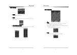
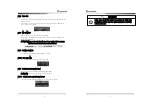
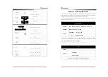
3.3.16 To change the way of bearing display 

1. True Bearing 
  Menu 

 System 

 Bearing Display 

 Input 

 True Bearing 

 Input 

 Esc   

 True bearing indication is set based on true north with scale 0. 

 It requires the equipment like GYRO COMPASS. 

2. Magnetic Bearing 

  Menu 

 System 

 Bearing Display 

 Input 

 Magnetic Bearing 

 Input 

 Esc 

 Magnetic Bearing indication is set based on Magnetic North with Scale 0. 

 MAGNET COMPASS is needed. 


3.3.17 To change the way of displaying bearing line/cursor. 

When you display the value of EBL bearing, select between the own ship and   

True North as a base.     

1.  Relative  Indication 

  Menu 

 View 

 EBL/Cursor 

 Input 

 Relative 

 Input 

 Esc 

 Make the cursor and the bearing value of EBL indicate based on ship s   

heading line (Ship s head line is 0) 

4.


True North Indication 

  Menu 

 View 

 EBL/Cursor 

 Input 

 True North 

 Input 

 Esc 

 Make the cursor, the bearing value of EBL indicate based on True North   

(True North is  0 ) 


3.3.18 To compensate the magnetic 

Enter  the  value  of  compensation  because  Magnetic  North  Bearing  is  slightly 

different according to the navigation zone. 

Menu 

 System 

 Magnetic Compensation 

 Input 

 Enter the value by cursor 

 Input 

 Esc 

 Enter the value manually.   

 Enter the value using direction key.(99.9  W ~ 99.9  E) 

 Direction key will shifted by 

±

0.1 with     and 

±

 1.0 with 


38 


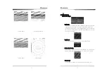
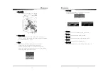
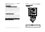
3.3.19 To display the trace of the target. 

 It may ascertain the other ship s movement in track line distance and   

direction. It facilitates to avoid collision of the ship. 

 The longer target track line ls displayed, the faster the other ship s speed is   

and vice versa. 

 The length of the track line is displayed ranging from 1 to 4 cycles.   

1. Activation of the target trace 

  Menu 

 Echo 

 Target trace 

 Input 

 1~4 

 Input 

 Esc or TRAIL 

 The revolution of the Antenna will be displayed from 1 to 4 cycles. 

 The color of the tarket track line will be changed in each cycle. 

 On the upper left side of the screen, the status (W1~W4) will be displayed. 

2. Deactivation of the target trace 

  Menu 

 Echo 

 Target Trace 

 Input 

 OFF 

 Input 

 Esc or TRAIL   


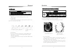
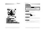
3.3.20 To display ECHO image wider on the radar screen. 

      To expand the ECHO image, use the following steps 

 Use the function of the target expansion.   

 Set the width of TX Pulse long. 

1. Activation of the target expansion 

  Menu 

 Echo 

 Target Expansion 

 Input 

 1~2 

 Input 

 Esc   

 The size of the target on the screen will be doubled. 

        2. Deactivation of the target expansion 

  Menu 

 Echo 

 Target Expansion 

 Input 

 OFF 

 Input 

 Esc 

 It will turn back to the original status, 


When designating the target magnification and wider transmit pulse width, the 

images  over  two  targets  accessed  from  fore  and  after  direction  and  angle 

direction.


Caution 

Содержание SMR-7200

Страница 1: ...nge Ring 28 3 3 8 To remove the Radar Interference 28 3 3 9 To elemina e he Ship Heading Line 29 3 3 10 To use the parallel line 29 3 3 11 To move the center of own ship 29 3 3 12 To measure the dista...

Страница 2: ...itor This radar complies with the regulation of frequency law 1 2 Feature Antenna Unit It emits the miscrowave toward targets by 4 four step pulse widths according to the radar scale and transfers the...

Страница 3: ...ription Q y Samyung CODE Remark Manual 1 SMR 7200 ME ANTENNA DISPLAY CABLE 1 RSU 7200 15M 15m POWER CABLE 1 ACC CAB 010 3m SURGE CABLE 1 STR 595 3m 6 1 4 Construction 1 2 0 0 386 466 Pic 1 1 RSU 7200...

Страница 4: ...25m Bearing Accuracy 1 Bearing Resolution 2 1 Bearing Input True Bearing Magnetic Bearing Environmental Condition 1 Temperature Antenna 25 55 Display 15 55 2 Relative Humidity Antenna below 5 on 35 Di...

Страница 5: ...c Switchable Bearing Scale 1 cale 360 Bearing Display Electronic Type Front Panel 1 Tune Knob 2 Gain Knob Switch 3 Rain Snow Removal Knob Switch 4 Sea Cluter Removal Knob Switch 5 Guard Switch 6 Dista...

Страница 6: ...ove the image center To adjust snow and rain clutter 1 To adjust the guard of the receiving signal To adjust sea clutter BRILL ENT TX RANGE ESC OFF CENT IR F EBL VRM 2 P LINE RING EBL VRM SEA CL GAIN...

Страница 7: ...Composition You may change the language to Korean English and others Press MENU and select any wishful setup menu by using direction button There are total of five 5 different menus and each menu fun...

Страница 8: ...tion will operate by pressing TRAIL RPM may be adjusted from Off to 4 Current setting status of W1 W2 will be displyed on the upper left corner of the screen Target boost Set and adjust the target boo...

Страница 9: ...tance setting and TCPA is setting for estimated time before collision CPA Menu TCPA Menu 18 2 3 2 3 Display setting Mode This menu allows to display bow N UP C UP and True Motion Bow mode only availab...

Страница 10: ...functions Cursor Lock and Cursor Float Cursor Lock Zooms up the area around the cursor you have entered Cursor Float Zoom up where the cursor is 20 Sector Blank You may set Sector Blank in the radius...

Страница 11: ...elects AIS heading standard as HDT or COG 22 2 3 2 5 System setting Language setting User may select a language Distance unit You may choose among nm mi km Compass Type You may select radar image with...

Страница 12: ...onsolidated and displayed user may judge the ideal time for repair It indicates the version of the program Refer When unit does not turn off due to programme failure Please push OFF switch for 10 seco...

Страница 13: ...n Menu System Languange Select user s language Input Return Select language 3 3 Basic Operation 3 3 1 TX Press T X button it will be converted to TX from the stand by status 3 3 2 TX Stop Press T X bu...

Страница 14: ...ntact by high gain 28 3 3 5 In order to remove the interference of rain snow Under heavy rain snow the target may be difficult to analyze since ECHO Rain Clutter caused by rain and snow may be display...

Страница 15: ...ssel and dangerous things as well as the wave images being suppressed When you use the removal function of Sea Level Wave you make sure it should be the optimistic set of suppression 30 3 3 7 To opera...

Страница 16: ...line key 2 To adjust the distance and the bearing use the diagonal key as follows key may adjust the bearing of the parallel line key may adjust the distance of the parallel line 3 3 12 To move the c...

Страница 17: ...the radar screen The value of distance and bearing will appear at the bottom end of the screen where the cursor is located 3 3 14 To change the distance unit 1 NM Nautical Mile Menu System Distance un...

Страница 18: ...to the right When the own ship turn right to 35 degree 36 3 Indication of course up C UP Menu View Mode Input Course Input Esc Make the ship s head line on the screen when the course up is excuted Ev...

Страница 19: ...9 W 99 9 E Direction key will shifted by 0 1 with and 1 0 with 38 3 3 19 To display the trace of the target It may ascertain the other ship s movement in track line distance and direction It facilitat...

Страница 20: ...2 NMEA 6 NMEA2 TX 8 GND 7 NMEA2 RX CABLE 8 4 5 6 7 1 3 5 12V OUT 2 GND 1 SHIELD 3 NMEA1 TX 4 NMEA1 RX DATA NMEA DOWNLOAD NMEA 5 12V OUT 2 GND 4 AIS TX 6 AIS RX 7 AIS RX 3 AIS TX 1 SHIELD CABLE AIS AI...

Страница 21: ...mind 10m 5m 3m 10NM 10NM The island which is not displayed on Screen 42 4 2 Reflection from the target The strength of reflection from the target is related to not only the size of the target but the...

Страница 22: ...ocated that uses the same frequency the interference image by the radar appears on PPI screen This interference turns into various spots and appear in forms of many images but as the interference does...

Страница 23: ...em 2 Caution while the Antenna is installed in Yacht It is apt to be sliding in slant toward the counter windy side while the yacht is navigating when the wind is blowing to the extent In case the sla...

Страница 24: ...ck pannel 2 Connect an Aireal cable to ANTENNA of the back pannel 3 Connect an earth cable to EARTH of the back pannel 5 4 Installation check After installation check that all job has followed the ins...

Страница 25: ...gree from 0 to 360 degrees and change it by 1 degree 5 6 3 0 Mile Set After installed the Antenna it depends on cable and or device you may adjust a real distance and target distance by adjusting 0 Mi...

Страница 26: ...g object accuracy will decrease and system speed may be decrease 5 6 8 Software Upgrade This menu will upgrade previouse software program 5 6 8 1 Stc Curve Min STC Curve e ing s minimum value is as 1...

Страница 27: ...agnetron 6 2 1 OpenArray 1 In case OpenArray surface being contaminated by dust paint it may arise the attenuation or reflection of electric wave and may cause decrease of the performance of Radar it...

Страница 28: ...55 Chapter 7 Installation drawing and circuit diagram 56 Antenna Unit RSU 7200...

Страница 29: ...SMR 7200 1 CODE NO SMR 7200 2 Bracket 1 CODE NO ACC RADAR 001 3 Knob 6 20 2 CODE NO ACC 6X18MM 002 4 Antenna RSU 7200 1 CODE NO RSU 7200 5 Antenna Cable SAMYUNG 11 X 16C 1 Cap SRCN2A 25 16P L 15m CODE...

Страница 30: ...MR 7200 This manual includes the proper way of operating and installing the unit and warnings Please keep this manual in a safe place Please pass the manual in case of selling or handing over to a new...

Отзывы: