


27
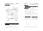
3.3.4 Gain control
Turn gain key.
When you turn key left, decreases the gain, when you turn right,
increases the gain.
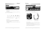
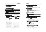
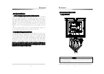
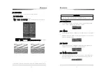
The optimum gain
Is when the target s ECHO display is at its maximum size, and when close by
targets are not touching on ECHO display
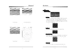
감도가 낮아 영상이 작다.
감도가 최적이다.
감도가 높아 2개의
영상이 붙었다.
Auto gain setting
When you push the switch in the gain volume, it will be displayed AUTO in
the bottom centre of the screen, it will be displayed GAIN-A in the right
bottom corner of the screen.
This function adjusts the gain at its optimum level, however may be affected
by environment.
ATTENTION
※
It should be always observed by adjusting the optimum conditions.
※
If the gain is too low, the targets may not be displayed.
※
If too high, it may be an obstade in observation due to the noise increase on the display.
Small image by low gain Optimum gain
2 Images contact by
high gain
28
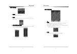
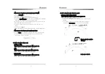
3.3.5 In order to remove the interference of rain/snow
!
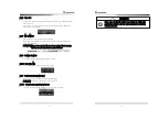
Under heavy rain/snow, the target may be difficult to analyze since ECHO
(Rain Clutter) caused by rain and snow may be displayed.
Turn Rain CL volume right to remove the echo image by snow and rain.
Reflected wave of rain/snow Removed rain/snow
(Target is restricted, too.)
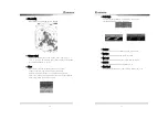
Auto setting rain/snow
When you push the switch in the volume for removal rain/snow, AUTO will
be displayed in Rain CL in the bottom center of the screen, and RAIN-A will
show on the bottom right corner of the display
This function is only to use under circumstances where the user wants to
automatically remove the snow/rain. Hence do not use this function if not
required as it will make target smaller than usual.
※
Too much adjustment of rain/snow removal will restrain the target of shipsor
hazards as well as any images by rain/snow. This can be the cause of image
analysis.
※
In case of use of rain/snow removal, the optimum conditions shoud alwaysset
up..
ATTENTION