Operating Instructions
11-4
Samsung Electronics
ENGLISH
78
78
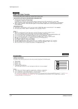
IEEE1394 Data Transfer
■
Connecting to other DV standard products.
A standard DV connection is quite simple.
If a product has a DV jack, you can transfer data by connecting to the DV jack using the correct cable.
NOTE: Please be careful since there are two types of DV ports, (4pin, 6pin). This Camcorder has a 4pin terminal.
■
With a digital connection, video and audio signals are transmitted in digital format, allowing high quality images
to be transferred.
■
If you want to transmit data to a PC, you must install an IEEE1394 add-on card into the PC. (not supplied)
■
The frame rate for video capture is dependent on the capacity of the PC.
[ Notes ]
■
When you transmit data from the Camcorder to another DV device, some functions may not work.
If this occurs, please reconnect the DV cable or turn the power OFF and ON again.
■
You cannot transmit data from the Camcorder to PC, when in M.Player mode. (VP-D453(i)/D454(i)/D455(i) only)
■
Do not use the Camcorder and IEEE1394 together as this will cause IEEE1394 to shut off.
■
Do not connect the Camcorder to a PC using both DV and USB cables. It may not operate properly.
■
Operation is not guaranteed for all computer environments recommended above.
■
The IEEE1394 cable (DV cable)is sold separately.
■
Video Capture software is commercially available.
■
Most DV enabled PCs have a 6 pin socket. In this case, a 6pin/4pin cable is required for the connection.
■
Most DV enabled Notebooks and Laptops have a 4 pin socket. Use a 4pin/4pin cable for the connection.
■
DIS and Color Nite are not available w
hen while in DV (IEEE1394) mode.
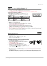
Connecting to a PC
Connecting to a DV Device
(DVD Recorder, Camcorder, etc.)
Transferring IEEE1394 (i.LINK)-DV standard data connections
ENGLISH
Preparation
23
23
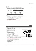
The battery level display indicates the amount of power remaining in the Battery pack.
a. Fully charged
b. 20~40% used
c. 40~80% used
d. 80~95% used
e. Completely used (Blinking)
(The Camcorder will turn off soon. Change the battery as soon as possible)
[ Notes ]
■
Please refer to the Table on page 22 for approximate continuous recording time.
■
The recording time is affected by temperature and environmental conditions.
■
The recording time shortens dramatically in a cold environment.
The continuous recording time in the operating instructions are measured using a fully charged Battery pack at 77 °F (25 °C)
since
the environmental temperature and conditions vary.
The remaining battery time may differ from the approximate continuous
recording time given in the instructions.
Battery Level Display
(Blinking)
Содержание VP-D455
Страница 10: ...Product Specification 2 4 Samsung Electronics MEMO...
Страница 30: ...3 20 Alignment and Adjustments Samsung Electronics MEMO...
Страница 46: ...4 16 Disassembly and Reassembly Samsung Electronics MEMO...
Страница 66: ...Exploded View and Parts List 5 20 Samsung Electronics MEMO...
Страница 83: ...Samsung Electronics 8 1 8 Wiring Diagram MEMORY STICK VP D453 I D6620I VP D454 I D455 I D6650I...
Страница 84: ...Wiring Diagram 8 2 Samsung Electronics MEMO...
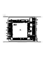
Страница 86: ...PCB Diagrams 9 2 Samsung Electronics 9 1 Main PCB COMPONENT SIDE...
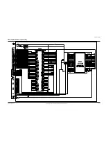
Страница 87: ...PCB Diagrams Samsung Electronics 9 3 L708 L704 L706 L717 L719...
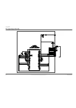
Страница 88: ...PCB Diagrams 9 4 Samsung Electronics CONDUCTOR SIDE Fuse 1 25A 32V...
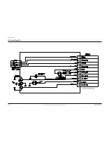
Страница 94: ...PCB Diagrams 9 10 Samsung Electronics MEMO...
Страница 114: ...Schematic Diagrams 10 20 Samsung Electronics This Document can not be used without Samsung s authorization MEMO...
Страница 128: ...Troubleshooting 12 8 Samsung Electronics MEMO...
Страница 140: ...Circuit Operating Description 13 12 Samsung Electronics MEMO...
Страница 184: ...Reference Information 14 44 Samsung Electronics MEMO...

