3-41
Samsung Electronics
CIRCUIT DESCRIPTION
Repair Manual
3-8-2 AC INPUT STAGE
AC Input power path is consist of the Fase (F501) for AC current limit, the Varistor (TNR501) for by-passing high Voltage
Surge, the discharge resistor(R508), the AC Impalse Noise Filtering Circuit (C501, LF501, C503), the Common Mode
Grounding Circuit (C504, C505), the 2’nd noise filter (LF502), and the thermistor (TH501).
Wher power is turned on, TH 501 limits Inlush-Current by it’s high resistanle, and When it’s temperature rise, it’s resistance
become about Zero ohm.
3-8-3 SMC(SWITCHED MODE CONTROL)
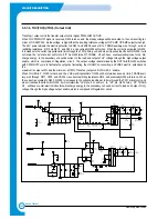
The AC input voltage is rectified and filtered by BD552 and C507 to create the DC high voltage applied to the primary wind-
ing of T501. TR01 pin #1 is driven by the SMPS device U502. U502. auto-starts and chops the DC voltage. The U502 is PWM
SMPS IC and has internally a SMC(switched mode control) IC and a MOSFET output stage. The SMC IC has a Auto-restart
without a Power Supply for the IC and a Thermal Shutdown function and so on. C509, R512, C510, D505 clamp leading-
edge voltage spikes caused by transformer leakage inductance.
The power secondary winding(pim #11-12)is rectified and filtered by D507, C552, L551, and C554 to create the 5V output
voltage. The bias winding(pin #4-5)is rectified and filltered by D506 and C511 to create U502 bias voltage. The secondary
output 5V is regulated through the path of the voltage divide by R553, R556-U503 switching PC252-the bias voltage of U502-
U503 PWM duty cycle-T501 secondary voltage. C508 filters internal pin, determines the auto-restart frequency, and togeth-
er with R506, compensates the control loop. U552 of the secondary stage -12Vis the Low Power-loss Regulator with built-in
overcurrent protection function
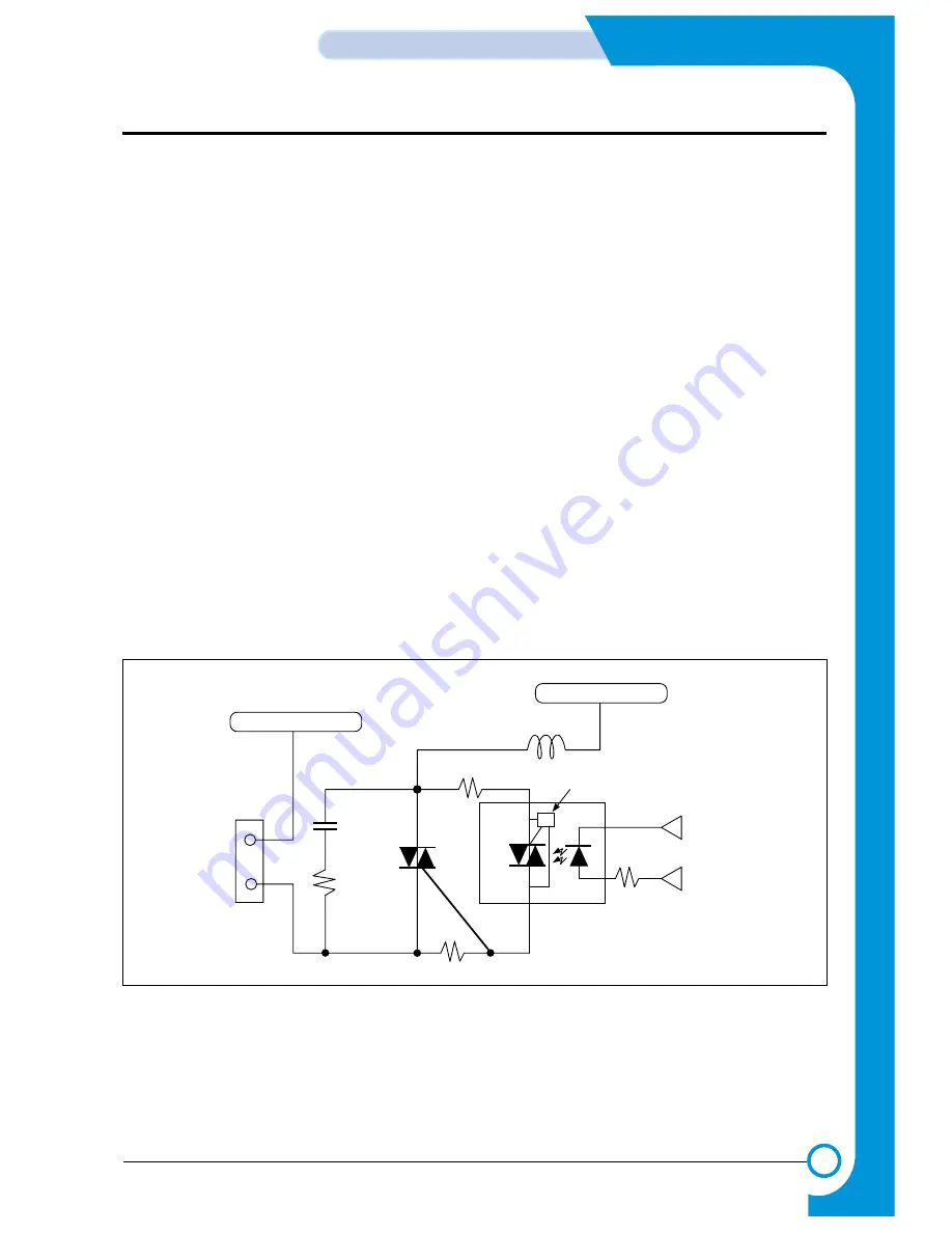
3-8-4. FIXED TEMPERATURE CONTROL
3-8-4-1. Fixed Lamp Control Circui
AC Neutral
AC Power Live
C502
R502
R503
R505
L501
Logic Unit
Fuser On
SMPS Unit
DC Power
U501
4
2
1
6
THY501
CON502
Zero crossing circuit
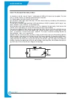
<Fixed Lamp Control Circuit>
Содержание SF-830
Страница 112: ...Exploded Views and Parts List 5 34 Samsung Electronics ...
Страница 116: ......
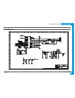
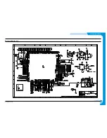
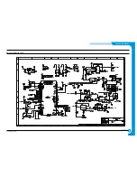
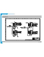
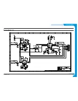
Страница 163: ...4 2 SCHEMATIC DIAGRAMS Samsung Electronics Repair Manual Main Circuit Diagram 2 17 ...
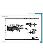
Страница 164: ...4 3 Samsung Electronics SCHEMATIC DIAGRAMS Repair Manual Main Circuit Diagram 3 17 ...
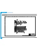
Страница 165: ...4 4 SCHEMATIC DIAGRAMS Samsung Electronics Repair Manual Main Circuit Diagram 4 17 ...
Страница 166: ...4 5 Samsung Electronics SCHEMATIC DIAGRAMS Repair Manual Main Circuit Diagram 5 17 ...
Страница 167: ...4 6 SCHEMATIC DIAGRAMS Samsung Electronics Repair Manual Main Circuit Diagram 6 17 ...
Страница 168: ...4 7 Samsung Electronics SCHEMATIC DIAGRAMS Repair Manual Main Circuit Diagram 7 17 ...
Страница 169: ...4 8 SCHEMATIC DIAGRAMS Samsung Electronics Repair Manual Main Circuit Diagram 8 17 ...
Страница 170: ...4 9 Samsung Electronics SCHEMATIC DIAGRAMS Repair Manual Main Circuit Diagram 9 17 ...
Страница 171: ...4 10 SCHEMATIC DIAGRAMS Samsung Electronics Repair Manual Main Circuit Diagram 10 17 ...
Страница 172: ...4 11 Samsung Electronics SCHEMATIC DIAGRAMS Repair Manual Main Circuit Diagram 11 17 ...
Страница 173: ...4 12 SCHEMATIC DIAGRAMS Samsung Electronics Repair Manual Main Circuit Diagram 12 17 ...
Страница 174: ...4 13 Samsung Electronics SCHEMATIC DIAGRAMS Repair Manual Main Circuit Diagram 13 17 ...
Страница 175: ...4 14 SCHEMATIC DIAGRAMS Samsung Electronics Repair Manual Main Circuit Diagram 14 17 ...
Страница 176: ...4 15 Samsung Electronics SCHEMATIC DIAGRAMS Repair Manual Main Circuit Diagram 15 17 ...
Страница 177: ...4 16 SCHEMATIC DIAGRAMS Samsung Electronics Repair Manual Main Circuit Diagram 16 17 ...
Страница 178: ...4 17 Samsung Electronics SCHEMATIC DIAGRAMS Repair Manual Main Circuit Diagram 17 17 ...
Страница 180: ...4 19 Samsung Electronics SCHEMATIC DIAGRAMS Repair Manual 4 3 OPE Circuit Diagram D9 ...
Страница 181: ...4 20 SCHEMATIC DIAGRAMS Samsung Electronics Repair Manual 4 4 Scan Circuit Diagram ...
Страница 187: ...4 26 SCHEMATIC DIAGRAMS Samsung Electronics Repair Manual 4 8 PTL Circuit Diagram ...
Страница 188: ...4 27 Samsung Electronics SCHEMATIC DIAGRAMS Repair Manual 4 10 Toner_Rx Circuit Diagram ...
Страница 189: ...4 28 SCHEMATIC DIAGRAMS Samsung Electronics Repair Manual 4 11 Toner_Tx Circuit Diagram ...

