

91
TROUBLESHOOTING
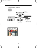
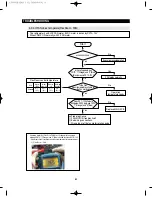
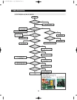
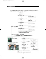
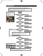
4-2-10. When refrigerator ROOM Lamp does not light up
When controlling the regrigerator light with Regulator(12V) : LED LAMP
→
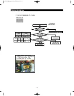
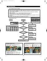
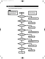
Applying to the FF/FZ/Mid Drawer compartment (Option)
* If the Vegetable Lamp does not work properly, check the FF compartment LED Lamp because it is
connected with the FF compartment LED Lamp in parallel. Refer to the circuit diagram to repair.
Start
Check/Replace REED S/W,
Magnet ASS
’
Y
Does the
DOOR S/W sense properly?
(Open/Close)
No
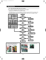
Replace/Repair the PCB
No
Replace/Rep air the PCB.
Repair IC76
No
Check the connector terminal
Replace PCB
No
Check the
connector terminal
No
Replace LED LAMP
Normal
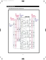
1) Measuring IC76 voltage(CN-”3” (Red)/FF LED) Measuring
IC77 voltage(CN78-"1"(Brown)/FZ LED) Measuring
IC78 voltage(CN78-"6"(White-Black)/Mid Drawer LED)
CN76-"12"(Purple) (FF Door Switch)
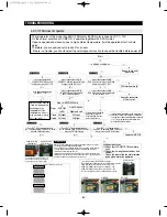
Typical PCB Ground REG1 Heater Sink
FF LED Lamp ON
Close
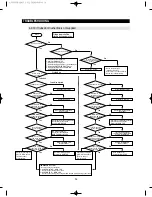
No
Check the wire
Re-insert the connector
No
Yes
Yes
Yes
Yes
Yes
Yes
Yes
Is the output
voltage of IC01 MICOM #52
normal?
Is the output
voltage of IC76
normal?
Is the MAIN
PCB connector(CN78) inserted
properly?
Does the MAIN
PCB connector(CN78) output
properly? (11~12V)
Is the LED LAMP
connected properly?
Is the LED LAMP normal?
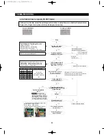
FF LED Lamp OFF
Open
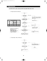
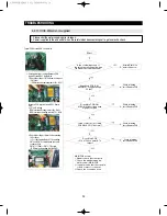
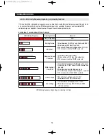
Door & MICOM State
Door
Close
Open
MICOM(#52)
Right and Left
0V(Low)
5V(High)
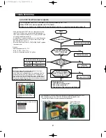
MICOM State
Door
(Right and
Left)
Close
Open
FF
#52
0V (Low)
5V (High)
FZ
#53
5V (High)
0V (Low)
Mid Drawer
#51
0V (Low)
5V (High)
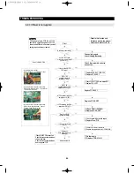
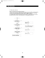
IC76(FF)/IC77(FZ)/IC78(Mid Drawer) State
IC76(FF)/IC77(FZ)/IC78(Mid Drawer)
0V(Low)
11~12V(High)
Micom
0V(Low)
5V(High)
AW3 SM-EN 2011.3.31 2:56 PM 페이지91 in
Содержание RF4287HARS
Страница 17: ...18 PRODUCT SPECIFICATIONS 2 5 Dimensions of Refrigerator Inches AW3SM EN2011 3 312 52PM 18 in...
Страница 20: ...21 PRODUCT SPECIFICATIONS 2 7 1 PRINCIPLE OF FREEZEER BACK CLUSTER PIPE AW3SM EN2011 3 312 52PM 21 in...
Страница 86: ...87 TROUBLESHOOTING IPM FREEWHEELING DIODE VOLTAGE VALUE AW3SM EN2011 3 312 56PM 87 in...
Страница 96: ...97 TROUBLESHOOTING SPM Internal DIODE Voltage AW3SM EN2011 3 312 56PM 97 in...
Страница 98: ...99 TROUBLESHOOTING INVERTER PCB Circuit Diagram AW3SM EN2011 3 312 56PM 99 in...
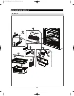
Страница 115: ...116 EXPLODED VIEW PARTS LIST 5 6 Disassembly of Door Refrigerator R 5 1 3 2 6 4 5 5 AW3SM EN2011 3 312 57PM 116 in...
Страница 122: ...123 6 3 Connector Layout with part position Main Board PCB DIAGRAM 6 3 1 RF4287HA AW3SM EN2011 3 312 57PM 123 in...
Страница 123: ...124 6 4 Connector Layout with part position Inverter Board PCB DIAGRAM 6 4 1 RF4287HA AW3SM EN2011 3 312 57PM 124 in...
Страница 124: ...125 7 1 Model RFG295AA BETTER 7 WIRING DIAGRAM BLU BLU AW3SM EN2011 3 312 57PM 125 in...
Страница 125: ...126 7 2 Model RF4287AA BEST 7 WIRING DIAGRAM AW3SM EN2011 3 312 57PM 126 in...
Страница 126: ...127 7 3 Model RFG299AA 7 LCD 7 WIRING DIAGRAM BLU BLU AW3SM EN2011 3 312 57PM 127 in...
Страница 127: ...128 7 4 Model RFG294AA SEARS 7 WIRING DIAGRAM AW3SM EN2011 3 312 57PM 128 in...
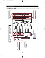
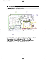
Страница 128: ...129 8 1 Whole block diagram 8 SCHEMATIC DIAGRAM 8 1 1 MAIN BLOCK RF4287 AW3SM EN2011 3 312 58PM 129 in...
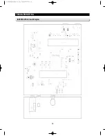
Страница 129: ...130 8 SCHEMATIC DIAGRAM 8 1 2 INVERTER BLOCK RF4287 AW3SM EN2011 3 312 58PM 130 in...
Страница 130: ...131 8 2 CIRCUIT DIAGRAM SCHEMATIC DIAGRAM 8 2 1 MAIN AW3SM EN2011 3 312 58PM 131 in...
Страница 131: ...132 SCHEMATIC DIAGRAM 8 2 2 INVERTER AW3SM EN2011 3 312 58PM 132 in...


