TROUBLESHOOTING
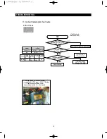
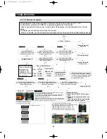
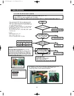
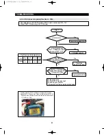
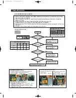
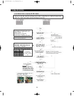
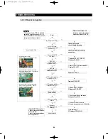
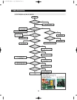
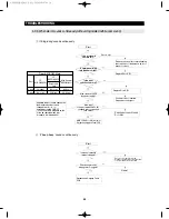
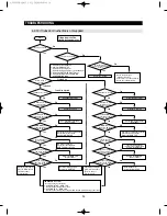
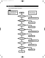
4-2-12. If Cubed or Crushed Ice is not supplied
93
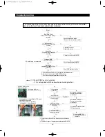
Start
①
Check the Ice making switch
②
Check the DOOR Switch
③
Check the Ice moving motor
④
Check the wiring connections of Ice moving motor
⑤
Check if the COVER ICE ROUTE opens
⑥
Check the Q706 movement related with
AUGER_MOTOR safety
①
Check the water pipe
: bending / Shut off
②
heck route of ice check solenoid
③
Check he Ice Maker wiring
Fridge door shall be
closed during operation.
If MAIN PCB is normal
- Need to check the other parts
①
AUGER MOTOR
↔
MAIN PCB
Check the door wiring connections.
②
CUBE MOTOR
↔
MAIN PCB
Check the door wiring connections/trouble their own or bad wiring connections.
Normal Operation status
Are Ices ejected?
Which mode is
selected?
Is Cubed Ice ejected?
No
Cubed Ice ejected
Crushed Ice
Cubed Ice selected
Is Cubed Ice mode
selected on the
panel PCB?
No
Cubed Ice
No
Yes
Yes
Yes
Yes
Yes
Yes
Yes
Check the wire connections/
Cube Solenoid
Is the CUBE MOTOR
positioned at cubed
ice mode?
No
- Check the Ice switch has trouble itself
- Check the wire connections
- Replace the MAIN PCB
- ICE S/W self diagnosis
- Check the connecting wires.
- MAIN PCB failure : Replace
Is MICOM IC01 #103
change into 0V when
press Ice switch?
No
Is the Dispenser
Cover opened?
No
Replace the MAIN PCB
(Errors on IC01)
Is IC73 #1,2 changed
into 5V when pressing
Ice Switch?
No
- RY7A, RY7B RELAY Error
- Replace the MAIN PCB
After disconnecting the
CN71, CN73 measure
The both ends of
Contact points.
After disconnecting the
CN71, CN73 measure
The both ends of
Contact points.
Is the contact
point of RY7A & RY7B RELAY
changed into 0
Ω
No
No
No
Yes
Yes
No
Yes
Yes
Yes
Yes
Yes
Yes
No
No
No
No
No
Normal Operation status
Cancel the “Ice Off”
Is Crushed Ice ejected?
Crushed Ice selected
Is Crushed Ice mode
selected on the
panel PCB?
Check the wire connections/
Motor Cube
Is the CUBE MOTOR
positioned at cubed
ice mode?
- Check the Ice switch has trouble itself
- Check the wire connections
- Replace the MAIN PCB
Is MICOM IC01 #103
change into 0V when
press Ice switch?
check the WIRE & Motor
check Cover ice route S/W 1,2
Replace the MAIN PCB
Is the Dispenser
Cover opened?
Replace the MAIN PCB
(Errors on IC01)
Is IC73 #2 changed
into 5V when pressing
Ice Switch?
- RY7A RELAY Error
- Replace the MAIN PCB
Is the contact
point of RY7A RELAY
changed into 0
Ω
Are Ices in the Ice bucket?
Is “Ice Off” mode
selected on the display
panel?
No
AW3 SM-EN 2011.3.31 2:56 PM 페이지93 in
Содержание RF4287HARS
Страница 17: ...18 PRODUCT SPECIFICATIONS 2 5 Dimensions of Refrigerator Inches AW3SM EN2011 3 312 52PM 18 in...
Страница 20: ...21 PRODUCT SPECIFICATIONS 2 7 1 PRINCIPLE OF FREEZEER BACK CLUSTER PIPE AW3SM EN2011 3 312 52PM 21 in...
Страница 86: ...87 TROUBLESHOOTING IPM FREEWHEELING DIODE VOLTAGE VALUE AW3SM EN2011 3 312 56PM 87 in...
Страница 96: ...97 TROUBLESHOOTING SPM Internal DIODE Voltage AW3SM EN2011 3 312 56PM 97 in...
Страница 98: ...99 TROUBLESHOOTING INVERTER PCB Circuit Diagram AW3SM EN2011 3 312 56PM 99 in...
Страница 115: ...116 EXPLODED VIEW PARTS LIST 5 6 Disassembly of Door Refrigerator R 5 1 3 2 6 4 5 5 AW3SM EN2011 3 312 57PM 116 in...
Страница 122: ...123 6 3 Connector Layout with part position Main Board PCB DIAGRAM 6 3 1 RF4287HA AW3SM EN2011 3 312 57PM 123 in...
Страница 123: ...124 6 4 Connector Layout with part position Inverter Board PCB DIAGRAM 6 4 1 RF4287HA AW3SM EN2011 3 312 57PM 124 in...
Страница 124: ...125 7 1 Model RFG295AA BETTER 7 WIRING DIAGRAM BLU BLU AW3SM EN2011 3 312 57PM 125 in...
Страница 125: ...126 7 2 Model RF4287AA BEST 7 WIRING DIAGRAM AW3SM EN2011 3 312 57PM 126 in...
Страница 126: ...127 7 3 Model RFG299AA 7 LCD 7 WIRING DIAGRAM BLU BLU AW3SM EN2011 3 312 57PM 127 in...
Страница 127: ...128 7 4 Model RFG294AA SEARS 7 WIRING DIAGRAM AW3SM EN2011 3 312 57PM 128 in...
Страница 128: ...129 8 1 Whole block diagram 8 SCHEMATIC DIAGRAM 8 1 1 MAIN BLOCK RF4287 AW3SM EN2011 3 312 58PM 129 in...
Страница 129: ...130 8 SCHEMATIC DIAGRAM 8 1 2 INVERTER BLOCK RF4287 AW3SM EN2011 3 312 58PM 130 in...
Страница 130: ...131 8 2 CIRCUIT DIAGRAM SCHEMATIC DIAGRAM 8 2 1 MAIN AW3SM EN2011 3 312 58PM 131 in...
Страница 131: ...132 SCHEMATIC DIAGRAM 8 2 2 INVERTER AW3SM EN2011 3 312 58PM 132 in...

