


70
TROUBLESHOOTING
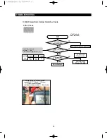
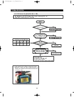
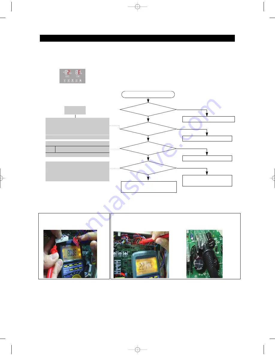
2) If R Sensor has trouble
Bad contact of connector/ insert correctly
Is MAIN PCB
Connector CN30 and CN76 inserted
correctly?
Is R Sensor
unit normal?
Is the voltage between
MAIN PCB Connector CN30#6(White) and
REG1 HEAT-SINK normal?
Is the input voltage of
IC01 MICOM #76 normal?
Start
NO
YES
YES
YES
YES
Replace the temperature sensor
NO
Recheck the wire connection part
NO(0.6V > Measurement < 4.6V)
Check the iced-solder, solder bridging,
disturbed solder.
NO
No trouble with PCB and temperature sensor.
Recheck the bad contact of the connection.
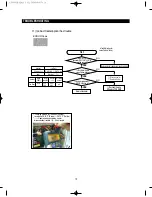
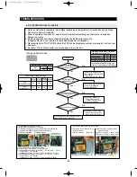
** Measuring point of resistance value according to
Sensor **
R : CN30#6
↔
CN76#1 measuring resistance value
** 0
Ω
: Short trouble /
∞Ω
: Open trouble
Sensor MICOM/Connector number
Voltage measured between 4.6V ~ 0.6V.
Measuring voltage IC01 MICOM #76,
CN30#6(White) and REG1, HEAT SINK
from PCB typical Ground part are similar.
→
Check the measure on the Resistance, R311 due
to the SMD MICOM
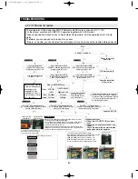
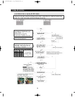
☞
Checking method of R Sensor resistance
CN30#6(White)
↔
CN76#1(Gray) Compare the
temperature table after measurment.
DATA1.
Temperature table
ERROR Code
Refer to circuit diagram in the manual
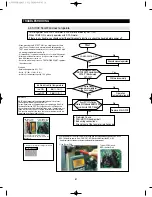
R
Connector CN30#6(White) to
REG1 HEAT-SINK PCB typical Ground
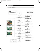
☞
Checking method of R Sensor resistance
- Measure the voltage of Sensor Check Point #3(IC01 MICOM
#76) on PCB or CN30#6(White)
↔
REG1, HEAT SINK
- Compare the temperature table after measurement.
Measuring voltage of CN30#6(White)
↔
REG1, HEAT SINK
are as below.
Typical PCB Ground
REG1, HEAT SINK
AW3 SM-EN 2011.3.31 2:56 PM 페이지70 in
Содержание RF4287HARS
Страница 17: ...18 PRODUCT SPECIFICATIONS 2 5 Dimensions of Refrigerator Inches AW3SM EN2011 3 312 52PM 18 in...
Страница 20: ...21 PRODUCT SPECIFICATIONS 2 7 1 PRINCIPLE OF FREEZEER BACK CLUSTER PIPE AW3SM EN2011 3 312 52PM 21 in...
Страница 86: ...87 TROUBLESHOOTING IPM FREEWHEELING DIODE VOLTAGE VALUE AW3SM EN2011 3 312 56PM 87 in...
Страница 96: ...97 TROUBLESHOOTING SPM Internal DIODE Voltage AW3SM EN2011 3 312 56PM 97 in...
Страница 98: ...99 TROUBLESHOOTING INVERTER PCB Circuit Diagram AW3SM EN2011 3 312 56PM 99 in...
Страница 115: ...116 EXPLODED VIEW PARTS LIST 5 6 Disassembly of Door Refrigerator R 5 1 3 2 6 4 5 5 AW3SM EN2011 3 312 57PM 116 in...
Страница 122: ...123 6 3 Connector Layout with part position Main Board PCB DIAGRAM 6 3 1 RF4287HA AW3SM EN2011 3 312 57PM 123 in...
Страница 123: ...124 6 4 Connector Layout with part position Inverter Board PCB DIAGRAM 6 4 1 RF4287HA AW3SM EN2011 3 312 57PM 124 in...
Страница 124: ...125 7 1 Model RFG295AA BETTER 7 WIRING DIAGRAM BLU BLU AW3SM EN2011 3 312 57PM 125 in...
Страница 125: ...126 7 2 Model RF4287AA BEST 7 WIRING DIAGRAM AW3SM EN2011 3 312 57PM 126 in...
Страница 126: ...127 7 3 Model RFG299AA 7 LCD 7 WIRING DIAGRAM BLU BLU AW3SM EN2011 3 312 57PM 127 in...
Страница 127: ...128 7 4 Model RFG294AA SEARS 7 WIRING DIAGRAM AW3SM EN2011 3 312 57PM 128 in...
Страница 128: ...129 8 1 Whole block diagram 8 SCHEMATIC DIAGRAM 8 1 1 MAIN BLOCK RF4287 AW3SM EN2011 3 312 58PM 129 in...
Страница 129: ...130 8 SCHEMATIC DIAGRAM 8 1 2 INVERTER BLOCK RF4287 AW3SM EN2011 3 312 58PM 130 in...
Страница 130: ...131 8 2 CIRCUIT DIAGRAM SCHEMATIC DIAGRAM 8 2 1 MAIN AW3SM EN2011 3 312 58PM 131 in...
Страница 131: ...132 SCHEMATIC DIAGRAM 8 2 2 INVERTER AW3SM EN2011 3 312 58PM 132 in...


