background image

16

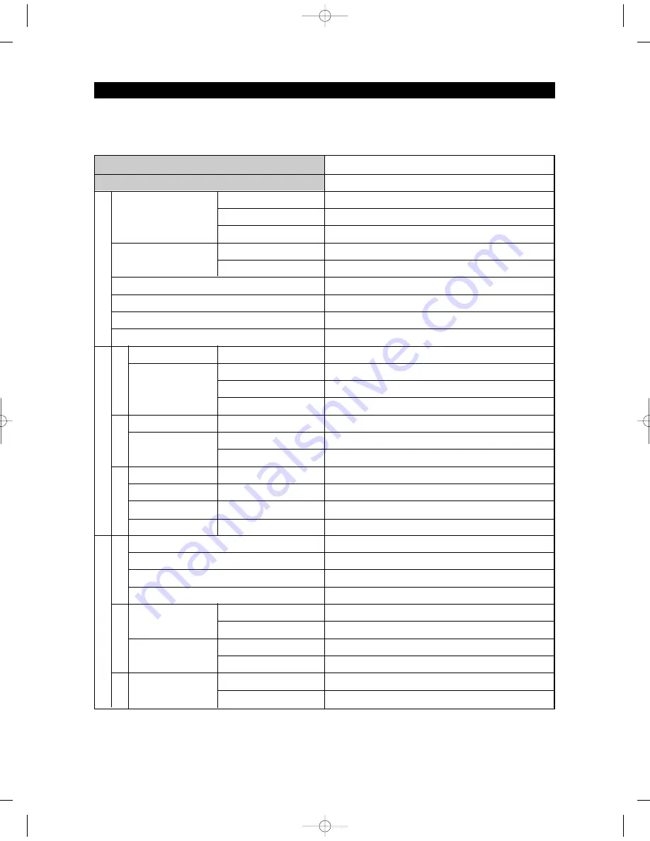
Items

Model

PRODUCT SPECIFICATIONS 

Compressor

Evaporator

Model

First Defrost Cycle (Concurrent defrost of F and R)

Defrost Cycle(FRE)

Defrost Cycle(REF)

Pause time

THERMISTOR

(F-SENSOR)

502AT

Temperature Selection

-8

(-22

)

-2

(-19

)

8

(-14

)

Model

THERMISTOR

(R-SENSOR)

502AT

F/R Defrost-

Sensor

F/R Bimetal-thermo

Protector

Temperature Selection

34

(1

)

38

(3

)

46

(7

)

Model

SPEC

Rated

Operating temperature

Condenser

Dryer

Capillary tube(Dia x Length)

Refrigerant

Model

Starting type

Oil Charge

Freezer

Refrigerator

MKV190C-L2B

BLDC

FREOL 

α

- 15c

SPLIT FIN TYPE

SPLIT FIN TYPE

Forced and Natural Convection Type

Molecular shieve XH-9

R : 0.032” x 118” (0.82mm x 3500mm) / F : 0.032” x 118” (0.82mm x 3500mm)

R134a

6hr 

±

10min

12~23hr(vary according to the conditions used)

6~11hr(vary according to the conditions used)

12 

±

1min

THERMISTOR (502AT)

5.0 

at 77

(25

)

AC 125V 10A

Off : 140

(60

) / On : 104

(40

)

F/R Fuse

Rated

Operating temperature

AC 250V 10A

Off: 230

(110

)

ON(

)

-5

(-20

)

1

(-17

)

11

(-12

)

ON(

)

36

(2

)

40

(4

)

48

(8

)

OFF(

)

-11

(-24

)

-5

(-21

)

5

(-15

)

OFF(

)

32

(0

)

36

(2

)

44

(6

)

Specification

RF4287HA

Components for Freezer

Defrost Related Components

Freezer

Refrigerator

Model

THERMISTOR

(F-SENSOR)

502AT

Temperature Selection

29

(-1

)

42

(5

)

ON(

)

32

(0

)

45

(7

)

OFF(

)

26

(-3

)

39

(4

)

Flex

Defrost Cycle

Defrost Sensor

Fuse

Room Temperature Sensor Components

AW3 SM-EN  2011.3.31 2:52 PM  페이지16    in

Содержание RF4287HARS

Страница 1: ...IGERATOR CONTENTS 1 PRECAUTIONS SAFETY WARNINGS 6 2 PRODUCT SPECIFICATIONS 10 3 DISASSEMBLY AND REASSEMBLY 27 4 TROUBLESHOOTING 56 5 EXPLODED VIEW PARTS LIST 105 6 PCB DIAGRAM 122 7 WIRING DIAGRAM 127...

Страница 2: ...personal injury and property damage The manufacturer or dealer cannot be responsible for the interpretation of this information SAMSUNG ELECTRONICS AMERICA INC Technical Service Guide Copyright 2010 A...

Страница 3: ...Filter 38 3 13 Water Tank 39 3 14 Motor Damper 41 3 15 Water Filter Assembly Disassembly 42 3 16 Vertical Hinged Section 43 3 17 Evaporator Cover In Refrigerator 44 3 18 Evaporator In Refrigerator 45...

Страница 4: ...current protecting circuit 100 4 3 2 power source hybrid ic 100 4 3 3 location sensing resistance area 101 4 3 4 sensing current area 101 4 3 5 comp operating signal area 102 4 3 6 bootstrap charging...

Страница 5: ...state before disassembly Check the use circumstance of refrigerator If the refrigerator is installed at the place that is damp or wet or status of installation is unstable change the installation plac...

Страница 6: ...Unplug Use the rated components on the replacement Check the correct model rated voltage rated current operating temperature and so on On repair make sure that the wires such as harness are bundled t...

Страница 7: ...rticles on the product Opening or closing the door may cause things to fall down which may cause injury Prohibition Warning Caution Do not allow users to disassemble repair or alter It may cause fire...

Страница 8: ...ooring This surface should be strong enough to support a fully loaded refrigerator or approximately 660lbs 299kg FLOORING Protect the finish of the flooring Cut a large section of the cardboard carton...

Страница 9: ...ecification Chart 15 2 5 Dimensions of Refrigerator Inches 18 2 6 Optional Material Specification 19 2 7 Refrigerant Route in Refrigeration cycle 20 2 7 1 Principle of freezeer 21 2 7 2 Operation theo...

Страница 10: ...and the refrigerator are cooled individually as required and are therefore more efficient Food odor from the refrigerator does not affect food in the freezer due to separate air flow circulation Coun...

Страница 11: ...er Flex zone and freezer door Slim Water Filtration System Touch Sensor Lighting Slim water filter is placed between crispers for changing filter conveniently without removing items from Refrigerator...

Страница 12: ...8 22 8 14 Run Time 60 80 Refrigerant Charge R134a 5 64 oz 160g MKV190C L2B 1314 Btu hr 0 385kw Compressor oil Freol 15c RCapillarytube Dia Length 0 032 118 0 0 8 82 2m mm m 3 35 50 00 0m mm m FCapilla...

Страница 13: ...er Dis Door Bins Cap Chute Vertical Hinged Section Slide Shelf Mid Door Bins Left Door Bins Tilting Pocket Light Vegetable Fruit Drawers Water Filter Right Door Bins Tempered glass shelves Light Auto...

Страница 14: ...lack Creamy STS Snow White Creamy STS Compressor Rated Frequency and Frequency Refrigerant Foaming Agent Refrigerant Input Amount Type Refrigerator Motor Rated Consumption Power Electric Heater Rated...

Страница 15: ...SPLIT FIN TYPE Forced and Natural Convection Type Molecular shieve XH 9 R 0 032 x118 0 82mmx3500mm F 0 032 x118 0 82mmx3500mm R134a 6hr 10min 12 23hr vary according to the conditions used 6 11hr vary...

Страница 16: ...amp LED Vegetable Lamp LED REF Eva Heated at F Defrost Heated at R Defrost Door Switch FRE REF Flex REF ICE ROOM Power Cord Earth Screw Specification RF4287HA Electric Components AC 120V 230W AC120V 1...

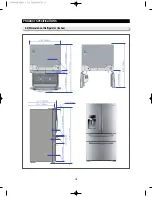
Страница 17: ...18 PRODUCT SPECIFICATIONS 2 5 Dimensions of Refrigerator Inches AW3SM EN2011 3 312 52PM 18 in...

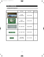
Страница 18: ...onal Material Specification Part Name Part Code AMOUNT FILTER WATER ASSY DA29 00020B DA99 00240S DA96 00398H DA96 00392C DA41 00519R 1 1 1 2 4 ASSY PACKING SUB LED LAMP REF LED LAMP SIDE LED LMAP CONV...

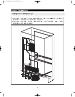
Страница 19: ...frigerator Evaporator Freezer Evaporator Suction Pipe Compressor 2 Compressor Condenser Hot Pipe Back Cluster Pipe Dryer Fre Capillary Tube Freezer Evaporator Suction Pipe Compressor PRODUCT SPECIFICA...

Страница 20: ...21 PRODUCT SPECIFICATIONS 2 7 1 PRINCIPLE OF FREEZEER BACK CLUSTER PIPE AW3SM EN2011 3 312 52PM 21 in...

Страница 21: ...product An old model Make them cluster at the lower part of product and radiate heat manually by fan Radiate condensed potential heat up to liquefy completely and make change the state without changin...

Страница 22: ...ure refrigerant gas flowed out from evaporator and make high temperature and pressure refrigerant liquid in the compressor and send it to the condenser 2 Type of Condenser a Back and forth motion type...

Страница 23: ...ction of synthetic insulating material insulator Influence of foreign substance Increase of condensed temperature Increase of temperature Decrease of cooling efficiency Shorten the life by friction be...

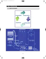
Страница 24: ...Cycle Type TDM Cycle Compressor Ref Hot Pipe 3Way Valve Ref Capillary Tube Fre Capillary Tube Ref Evaporator Fre Evaporator Accumulator Suction Pipe Connected Pipe Back Cluster Condenser Fre Hot Pipe...

Страница 25: ...26 Refrigerator PRODUCT SPECIFICATIONS 2 8 Cooling Air Circulation Freezer Flex Zone AW3SM EN2011 3 312 52PM 26 in...

Страница 26: ...se Water Filter 38 3 13 Water Tank 39 3 14 Motor Damper 41 3 15 Water Filter Assembly Disassembly 42 3 16 Vertical Hinged Section 43 3 17 Evaporator Cover In Refrigerator 44 3 18 Evaporator In Refrige...

Страница 27: ...ot install the refrigerator in a damp place or place where it may come in contact with water Deteriorated insulation of electrical parts may cause an electric shock or fire The refrigerator must be gr...

Страница 28: ...he tube fitting 6 apart as shown in the picture 3 Disconnect the electrical connector 3 above the upper left door hinge To disconnect the connector 3 more easily press the end of the hook 4 and pull c...

Страница 29: ...the lower left and right door hinges Remove the lower left and right door hinges 12 12 10 11 Refrigerator Door Part Name How To Do Descriptive Picture 5 1 Left door hinge With a Philips head screwdri...

Страница 30: ...art Name How To Do Descriptive Picture 1 Loose Set Screw with 0 1in Hex wrench and pull front the handle 2 Remove the cover vinyl of door DISASSEMBLY AND REASSEMBLY 3 3 Door Handle Refrigerator AW3SM...

Страница 31: ...rews 3 Lift up the handle to have the Slider Handle 1 pushed back 4 After having the Slider Handle 1 pushed back screw up at the hole 5 Remove the 4 Fixer Handle 2 by using the flat blade screwdriver...

Страница 32: ...pushing it to the right side and pulling it up Refrigerator Light Part Name How To Do Descriptive Picture 1 Remove the lamp cover by pushing a flat blade screwdriver Into the hooks behind and pull th...

Страница 33: ...cover 4 Take hooks 1 away from the groove using flat head screwdriver and pull it toward 2 to separate 3 7 Water Dispenser Water Dispenser Part Name How To Do Descriptive Picture 1 Disengage the Housi...

Страница 34: ...omplished 2 When assembling Cover Display first insert it from leftside and then assemble to rightside Check the wire inside and knock the display into the Case dispenser 3 8 Glass Shelf Glass Shelf P...

Страница 35: ...Vegetable Fruit Drawers Shelf Vegetable Fruit Shelf Part Name How To Do Descriptive Picture 1 Remove the vegetable fruit drawer by pulling the roller part and lifting it up 2 While pressing the butto...

Страница 36: ...compressor cover 1 Remove the water valve fixed by the screw 2 Remove the tube clip 3 and disconnect the water hose by pushing the fiting apart 3 Remove the tube clip 4 and disconnect the valve hose f...

Страница 37: ...located on the Case Water Filter Refer to the Vegetable Fruit Shelf 1 Remove 2 screws 2 a Disconnect the water fixer tube 1 on left top table Refer to the Refrigerator door push the flat blade driver...

Страница 38: ...ter Valve 5 Pick the Case Water Filter out 3 13 Water Tank Water Tank Part Name How To Do Descriptive Picture Before disassembling the Water Tank take the water filter 1 and water tray 2 out 1 Remove...

Страница 39: ...y pushing the flat blade driver 3 Cut the sponge stick on the Case Water tank and divide Case Water Tank 4 Remove the tube clips 3 and disconnect the water tank hoses by pulling the fitting tube 5 Be...

Страница 40: ...Damper Part Name How To Do Descriptive Picture 1 Remove the 2 screws under the water filter case and take off the cover damper 2 Disengage 2 housing connector 3 Take off the Motor Damper by pulling a...

Страница 41: ...ter Part Name How To Do Descriptive Picture 1 Turn the water filter count clockwise Refer to the picture 2 Remove the water filter by pulling it Refer to the picture 3 Push the water filter directly 4...

Страница 42: ...ve 2 screw cap parts with a flat blade screwdriver Refer to the picture 2 Unscrew 2 screws 3 Disengage the internal housing connector of the vertical hinge 4 Remove the vertical hinged section by lift...

Страница 43: ...ver Refer to the picture 2 Unscrew 4 screws 3 Remove the the lower part of angle mid by pulling it out and pushing it down Refer to the picture 4 Remove the hook by pulling it from the lower part and...

Страница 44: ...housing connector on right side 4 Remove the evaporator by lifting the bottom side of it up and pulling it out Refer to the picture 1 2 left left left left left left left left left left left left left...

Страница 45: ...en to full extension 2 Remove the brackets by pulling the them outside after separate the tilting Pocket 3 Take out the lower basket by lifting the basket up from rail system 4 Unscrew 4 bolts 2 bolts...

Страница 46: ...iver Refer to picture 7 Remove the Freezer Rail by pulling it 3 20 Convertible Door Mid drawer Part Name How To Do Descriptive Picture 1 Pull the and remove the convertible room by pulling it to your...

Страница 47: ...To Do Descriptive Picture 4 Unscrew 4 bolts 2 bolts each on the both sides 5 Lifting up the convertible door remove the convertible door from the rail 6 Remove the shaft gear 2 by pull the pin 2 out 7...

Страница 48: ...de screwdriver and pull it out 4 Disengage the 2 housing connectors 5 Push the hook and pull the Ice Maker out 6 To disassemble push the tab and pull the Case Auger and the motor out lever lever lever...

Страница 49: ...Picture 1 Remove the cover Flex zone lamp by a flat blade screwdriver 2 Disengage the housing 3 24 Freezer Light Freezer Light Part Name How To Do Descriptive Picture 1 Remove the cover Freezer lamp l...

Страница 50: ...a flat blade screwdriver 2 Separate the Side lamp from the case 3 Disengage the housing 3 26 Door Switch In Freezer Door Switch In Freezer Part Name How To Do Descriptive Picture 1 Remove the freezer...

Страница 51: ...t one 2 Remove the evaporator by pulling the lower part of the evaporator while lifting it up Evaporator Cover In Freezer Part Name How To Do Descriptive Picture 1 Remove the freezer door and freezer...

Страница 52: ...3 Remove the hooker of support circuit motor by lifting the hooker up and pulling it out 4 Remove the screw with a flat blade screwdriver Refer to the picture 5 Remove the motor fan by pulling the fa...

Страница 53: ...ge the housing connector 1 Unscrew 1 screw fixed on left 3 29 Machine Compartment Relay O L Part Name How To Do Descriptive Picture 1 Disengage the housing connector 2 Remove Cover Relay 3 Remove the...

Страница 54: ...ght door hinges with a phillps screwdriver 2 Disengage all housing connectors from the main PCB 3 Remove the main PCB by pushing the lower part of the hook down 4 Unscrew 2 PCB fixing screws 5 Remove...

Страница 55: ...er is not supplied 85 4 2 8 If compressor does not operate 86 4 2 9 When alarm sounds continuously without stop related with buzzer sound 88 4 2 10 If Mid Drawer Panel PCB does not work normally 90 4...

Страница 56: ...d one more time FF 3 will be displayed FF 2 and FF 3 means manual operation2 and 3 separately These 3 functions operate with different RPM of COMP 1 3 If manual operation is selected compressor will r...

Страница 57: ...ne more time defrosting of fresh food and freezer compartments will be canceled at the same time and will return to the normal operation Or all test functions will be canceled by turning main power ON...

Страница 58: ...ver Key Lighting Key are pressed simultaneously for 6 seconds during normal operation the temperature setting display will operate for 2 seconds ON OFF 0 5sec each If Energy Saver Key Lighting Key are...

Страница 59: ...or less than 58 F 50 Ice Room Sensor Error The voltage of MAIN PCB CN78 10 CN78 1 shall be between 4 5V 1 0V Display error during operation of applicable fan motor Feed back signal line contact error...

Страница 60: ...er Error After separating MAIN PCB CN77 wire from PCB resistance value between Black Brown wire shall be 135 ohm 7 0 ohm heater short Ohm wire bimetal Open Display error when open error is detected by...

Страница 61: ...it does not mean whether load is operating or not That is to say that though load operation is displayed load could not be operated by actual load error or PCB relay error etc This function would be a...

Страница 62: ...F 10 F 10 F 10 F 10 R FAN High R FAN Low R DEF Heater Start Mode Overload condition Low temperature condition Normal Condition Exhibition Mode COMP F FAN High F FAN Low F DEF Heater Mide Drawer Room D...

Страница 63: ...below Fresh food and freezer compartments case will be explained only because all options are operated with the same method according to the option table TROUBLESHOOTING If Freezer Key lighting Key ar...

Страница 64: ...than 4 2 0 C Refer to the picture changing the freezer compartment temperature 4 Option changing method as above is the same as all RF4287 model 5 By the same method as above it is possible to contro...

Страница 65: ...5 6 3 0 7 3 5 1 0 5 2 1 0 3 1 5 4 2 0 5 2 5 6 3 0 7 3 5 8 4 0 FZ compartment Code Settingvalue Temp compensation 0 1 2 3 4 5 6 7 8 9 10 11 12 13 14 15 0 0 0 1 0 5 2 1 0 3 1 5 4 2 0 5 2 5 6 3 0 7 3 5...

Страница 66: ...48 2 50 51 8 53 6 55 4 57 2 59 60 8 62 6 64 4 66 2 68 69 8 71 6 73 4 75 2 77 78 8 80 6 82 4 84 2 86 87 8 89 6 91 4 93 2 95 96 8 98 6 100 4 102 2 3 107 3 057 3 006 2 955 2 904 2 853 2 802 2 751 2 700 2...

Страница 67: ...83 1605 1627 1648 1669 1690 1712 1733 1754 1776 1797 1818 RH Output mV A D 10 bit A D 12 bit 46 47 48 49 50 51 52 53 54 55 56 57 58 59 60 61 62 63 64 65 66 67 68 69 70 71 72 73 74 75 76 77 78 79 80 81...

Страница 68: ...ire connection part NO 0 6V Measurement 4 6V Check the iced solder solder bridging disturbed solder NO No trouble with PCB and temperature sensor Recheck the bad contact of the connection Measuring po...

Страница 69: ...resistance value 0 Short trouble Open trouble Sensor MICOM Connector number Voltage measured between 4 6V 0 6V Measuring voltage IC01 MICOM 76 CN30 6 White and REG1 HEAT SINK from PCB typical Ground...

Страница 70: ...ng resistance value 0 Short trouble Open trouble Sensor MICOM Connector Number Voltage measured between 4 6V 0 6V Measuring voltage of IC01 MICOM 78 CN30 8 Sky blue and REG1 HEAT SINK from PCB typical...

Страница 71: ...p table of upper hinge 0 Short trouble Open trouble Sensor MICOM Connector number Voltage measured between 4 6V 0 6V Measuring voltage of IC01 MICOM CN78 8 Yellow and REG1 HEAT SINK from PCB typical G...

Страница 72: ...ce value 0 Short trouble Open trouble Sensor MICOM Connector number Voltage measured between 4 6V 0 6V Measuring voltage of IC01 MICOM 74 CN30 3 Red and REG1 HEAT SINK from PCB typical Ground part are...

Страница 73: ...e 0 Short trouble Open trouble Sensor MICOM Connector number Voltage measured between 4 6V 0 6V Measuring voltage of IC01 MICOM 75 CN30 5 Orange and REG1 HEAT SINK from PCB typical Ground part are sim...

Страница 74: ...trouble Open trouble Sensor MICOM Connector number Voltage measured between 4 6V 0 6V Measuring voltage of IC01 MICOM 90 CN78 10 Orange and REG1 HEAT SINK from typical PCB Ground are similar Check th...

Страница 75: ...istance value 0 Short trouble Open trouble Sensor MICOM Connector number Voltage measured between 4 6V 0 6V Measuring voltage of IC01 MICOM 81 CN30 9 Yellow and REG1 HEAT SINK from PCB typical Ground...

Страница 76: ...ccording to Sensor Humidity CN30 1 3 Resistance value with opened about 50 0 Short trouble Open trouble Sensor MICOM Connector number Voltage measured between 3 5V 1 0V Measuring voltage of ICO1 MICOM...

Страница 77: ...eplace PCB MAIN NO Normal recheck Measure the resistance between after CN77 connector open 135ohm 7 ERROR Code Checking method of Flex Room Damper resistance CN77 1 Black 2 Brown Open wire disconnecti...

Страница 78: ...wire 2 Replace PCB MAIN NO Normal recheck ERROR Code Checking method of Flex Room Damper resistance CN51 2 Brown CN79 2 Yellow Open wire disconnection heater disconnection trouble 0 Short trouble Star...

Страница 79: ...estart four times more If signals are not entered continuously the motor will be restarted after 10 Minutes This function is effective when the normal operation of motor would be restrained by foreign...

Страница 80: ...mplished After beginning of TEST mode Ice maker heater turns on for initial 2 minutes if the ice making temperature is below 0 If it exceeds 0 Ice maker heater turns on for initial 30 seconds After Ic...

Страница 81: ...n motor rotation pulse Is the voltage between CN79 1 Orange and 3 Blue Black around DC10 12V Does DC7 12V alternate with below DC2V between CN79 1 Orange and 3 Blue FAN works normally Operation temper...

Страница 82: ...G1 Heater Sink Displays ERROR Code Start 1 Replace the Ice Maker Kit 2 Check Replace the Main PCB input signal Micom IC01 Pin 37 0V DoesIceMaker rotatewhenpressingtheIceMaker testing switch over 1 5 s...

Страница 83: ...and freezer compartments are higher than 50 10 53 6 12 by the heating from heater heating would be finished and will return to cooling operation after a pause Check bimetal heater itself disconnectio...

Страница 84: ...e connections between door and panel PCB 1 Check the contact of lead wire 2 Replace the applicable relay PCB MAIN 1 Check PCB PATTERN and replace BD1 2 Replace PCB ASS Y Is the plug connected in Is po...

Страница 85: ...replace PCB No Yes No Yes Yes Yes Yes Yes Yes Yes Yes Yes Yes Does compressor work with manual operation Is CN75 PIN 4 High 2 5V Is the wiring between Main and Sub normal Is the connector between Mai...

Страница 86: ...87 TROUBLESHOOTING IPM FREEWHEELING DIODE VOLTAGE VALUE AW3SM EN2011 3 312 56PM 87 in...

Страница 87: ...tions of interferance by door gasket food etc Replace Door S W Repair wire connection and Door S W Normal Recheck and Replace Panel PCB MAIN PCB Door S W is normal Recheck and replace Panel PCB Sepera...

Страница 88: ...re associated with panel is occurred except the minor error such as switch pressing error surface peeling off and so on Start Does it sound dingdong if press a button on the front panel Is there any d...

Страница 89: ...in MAIN PCB Check voltage Replace MAIN PCB Panel PCB itself has trouble Reassemble PCB ASS Y Enforce the cancelation of pressed keys Reassemble PCB ASS Y Enforce the cancelation of pressed keys Conve...

Страница 90: ...3 Red FF LED Measuring IC77 voltage CN78 1 Brown FZ LED Measuring IC78 voltage CN78 6 White Black Mid Drawer LED CN76 12 Purple FF Door Switch Typical PCB Ground REG1 Heater Sink FFLEDLampON Close No...

Страница 91: ...ort Replace PCB Check soldering short Replace PCB Check soldering short Replace PCB Typical PCB Ground REG1 Heater Sink Checking method of voltage Based on PCB typical Ground REG1 Heater Sink 1 Check...

Страница 92: ...onnecting wires MAIN PCB failure Replace Is MICOM IC01 103 change into 0V when press Ice switch No Is the Dispenser Cover opened No Replace the MAIN PCB Errors on IC01 Is IC73 1 2 changed into 5V when...

Страница 93: ...use personal injury 3 Motor will rotate continuously when the Motor Switch is not sensed Main PCB Check the wire OPEN SHORT between the Cover Ice Motor Rotation sensing switches Check the Short of Cov...

Страница 94: ...IN PCB down Yes No Check PCB PATTERN Replace BD1 Is DC 300V applied between both ends of BD1 No Yes Replace PCB ASS Y Is DC300V applied to HYBRID IC 10 PIN No Yes 1 Replace HYBRID IC IC3 BP5047B15 2 R...

Страница 95: ...rrent Detection Motor Locked Over RPM Under Voltage Over Voltage Remarks N A 1 Short between COMP U V and W phase CN301 2 Short among IPM Pins No 1 33 3 Drop the IPM operating Voltage under DC 13 5V 4...

Страница 96: ...97 TROUBLESHOOTING SPM Internal DIODE Voltage AW3SM EN2011 3 312 56PM 97 in...

Страница 97: ...It supplied DC15V and 5V to MICOM 3 Location sensing resistance area It senses motor location through the current detected 4 Current sensing area It senses the current from the SHUNT resistance and c...

Страница 98: ...99 TROUBLESHOOTING INVERTER PCB Circuit Diagram AW3SM EN2011 3 312 56PM 99 in...

Страница 99: ...Hybrid IC and supplied to operate the MICOM for controlling COMP and SPM 100 TROUBLESHOOTING 4 3 1 INRUSH CURRENT Protecting Circuit 1 The Power Thermistor prevents an instant inrush of current genera...

Страница 100: ...and the converted value as voltage about 0 5V is applied to the MICOM PIN 18 101 TROUBLESHOOTING 4 3 3 Location Sensing Resistance Area 1 The circuit makes an AD conversion from MICOM for about 3 3V t...

Страница 101: ...nd is constituted as 3 Capacitors and charges the capacitors by turning the Low Side Power Switch On just before starting the motor for a certain period of time 1000ms 102 TROUBLESHOOTING 4 3 5 Comp O...

Страница 102: ...ezer 106 5 2 Refrigerator 108 5 3 Cabinet 111 5 4 Disassembly of Door Refrigerator L 114 5 5 Disassembly of Door Refrigerator R 115 5 6 Disassembly of Door freezert 198 5 7 Disassembly of Flex Zone Do...

Страница 103: ...104 EXPLODED VIEW PARTS LIST 5 1 Freezer 1 12 4 7 7 2 7 1 8 6 4 1 4 3 4 2 3 9 5 11 10 2 1 1 1 2 1 3 12 3 12 2 12 6 12 5 12 1 12 4 AW3SM EN2011 3 312 56PM 104 in...

Страница 104: ...L SHAFT GEAR CAP DOOR HANDLE ASSY RAIL SLIDE LOW R FIXER GEAR GEAR RAIL R COVER RAIL LOW R SWITCH DOOR F GUIDE DRAWER BOX ASSY TRAY DRAWER BOX ASSY COVER EVAP FRE FAN BACKWARD MOTOR BLDC HEATER CORD D...

Страница 105: ...3 24 2 24 1 24 25 25 2 25 3 25 4 15 19 30 31 29 27 8 3 9 9 1 31 1 31 2 13 19 1 19 3 19 2 14 11 12 26 22 11 22 12 22 7 22 8 22 5 22 6 22 10 22 3 22 9 22 13 22 1 22 2 29 1 17 18 25 1 4 2 1 7 5 5 2 5 1...

Страница 106: ...LED SIDE SHAFT GEAR CONV ASSY EVAP REF SENSOR TEMP FIXER SENSER HEATER METAL SHEATH THERMO FUSE ASSY ASSY RAIL VEG L ASSY RAIL VEG R ASSY COVER VEG REF KNOB HUMIDITY LEVER HUMIDITY ROLLER FRE CASE LA...

Страница 107: ...R GEAR GEAR R SWITCH REED ASSY COVER FIXER HOUSING V COVER HARNESS ICE ROOM ASSY CASE AUGER MOTOR SENSOR TEMP SPRING ETC SOLENOID SLIDER SOLENOID DISP BUSH SOLENOID GEAR SOLENOID FIXER NUT VALVE SOLEN...

Страница 108: ...12 13 34 37 35 28 39 31 27 32 17 16 25 2 19 5 19 19 5 1 8 1 4 2 1 4 1 4 1 4 2 11 18 2 3 2 3 23 3 9 40 15 2 4 2 2 2 2 2 1 2 1 1 38 1 2 1 3 1 1 15 1 15 1 15 2 15 2 19 6 19 2 19 3 19 4 19 1 20 5 7 22 14...

Страница 109: ...PE B PIPE CONNECT DISC B ASSY CAP DRAIN ASSY MOTOR STEP VALVE WIRE HARNESS STEP VALVE ASSY CHASSIS COMP CASTER REAR SHAFT CASTER ASSY COVER COMP ASSY COVER PCB PANEL ASSY PIPE CONNECT ASSY TRAY DRAIN...

Страница 110: ...INGE UPP R ASSY HINGE MID L ASSY HINGE MID R ASSY HINGE UPP L ASSY HINGE UPP L ASSY HINGE UPP L ASSY TOP TABLE ASSY TOP TABLE ASSY TOP TABLE TUBE FITTING B FIXER HOSE FIXER HOSE ASSY PIPE WATER ASSY C...

Страница 111: ...12 EXPLODED VIEW PARTS LIST 5 4 Disassembly of Door freezer 1 11 1 4 1 5 1 6 1 3 1 1 1 10 1 13 1 15 1 2 2 4 2 3 2 2 2 1 1 9 1 14 1 9 1 3 1 1 1 12 1 7 1 6 1 8 1 2 1 2 1 10 AW3SM EN2011 3 312 57PM 112 i...

Страница 112: ...CAP HANDLE CAP HANDLE CONV L CAP HANDLE CONV L CAP HANDLE CONV L CAP HANDLE CONV R CAP HANDLE CONV R CAP HANDLE CONV R SUPPORT DOOR POSITION IN SPRING ETC EASY HANDLE ASSY DOOR FOAM FRE ASSY DOOR FOAM...

Страница 113: ...EW PARTS LIST 5 5 Disassembly of Door Refrigerator L 9 6 7 11 8 11 1 10 7 10 4 10 2 10 1 4 10 6 10 5 5 7 1 7 7 1 7 1 4 9 2 9 1 1 2 3 7 1 3 7 1 2 7 1 6 7 1 5 7 1 1 8 1 8 2 4 10 3 12 10 AW3SM EN2011 3 3...

Страница 114: ...SUPPORT DOOR CLOSE SUPPORT DOOR CLOSE STOPPER DOOR L MAGNET COVER CAP DOOR LED GROMMET STOPPER CAM AUTO CLOSE L CAM AUTO CLOSE L CAM AUTO CLOSE L ASSY CAP CHUTE ICE GASKET CAP CHUTE ICE CAP CHUTE ICE...

Страница 115: ...116 EXPLODED VIEW PARTS LIST 5 6 Disassembly of Door Refrigerator R 5 1 3 2 6 4 5 5 AW3SM EN2011 3 312 57PM 116 in...

Страница 116: ...R HANDLE ASSY DOOR FOAM REF R ASSY DOOR FOAM REF R ASSY DOOR FOAM REF R ASSY DOOR FOAM REF R HANDLE BAR REF ASSY HANDLE BAR REF ASSY HANDLE BAR REF ASSY GASKET DOOR REF ASSY GASKET DOOR REF ASSY GUARD...

Страница 117: ...EXPLODED VIEW PARTS LIST 5 7 Disassembly of Flex Zone Door 1 2 2 19 2 7 2 3 2 2 2 15 2 12 2 6 2 11 2 15 2 9 2 8 2 12 2 6 2 3 2 2 2 1 2 10 2 17 2 13 2 14 2 18 2 5 2 4 2 16 AW3SM EN2011 3 312 57PM 118...

Страница 118: ...DLE R COVER HANDLE R COVER HANDLE R COVER CAP DOOR LED COVER CONTROL WINDOW CONV INLAY COVER CONTROL CONV INLAY COVER CONTROL CONV INLAY COVER CONTROL CONV SHAFT CAP HANDLE CAP HANDLE CONV L CAP HANDL...

Страница 119: ...ition 121 6 2 PCB Layout with part position Inverter Board 122 6 3 Connector Layout with part position Main Board 123 6 3 1 RF4287HA 123 6 4 Connector Layout with part position Inverter Board 124 6 4...

Страница 120: ...ied voltage 7 PLC input output PLC Power Line communication Option PLC module is not inserted unless specified occasion 8 Operate ICE MAKER supply power to MOTOR and sense the variation of switch 9 Ma...

Страница 121: ...ybrid IC It supplies DC15V and 5V to MICOM 3 Current detecting area It detects the current from the SHUNT resistance and controls PWM DUTY 4 COMP operating Signal area It receives COMP operating signa...

Страница 122: ...123 6 3 Connector Layout with part position Main Board PCB DIAGRAM 6 3 1 RF4287HA AW3SM EN2011 3 312 57PM 123 in...

Страница 123: ...124 6 4 Connector Layout with part position Inverter Board PCB DIAGRAM 6 4 1 RF4287HA AW3SM EN2011 3 312 57PM 124 in...

Страница 124: ...125 7 1 Model RFG295AA BETTER 7 WIRING DIAGRAM BLU BLU AW3SM EN2011 3 312 57PM 125 in...

Страница 125: ...126 7 2 Model RF4287AA BEST 7 WIRING DIAGRAM AW3SM EN2011 3 312 57PM 126 in...

Страница 126: ...127 7 3 Model RFG299AA 7 LCD 7 WIRING DIAGRAM BLU BLU AW3SM EN2011 3 312 57PM 127 in...

Страница 127: ...128 7 4 Model RFG294AA SEARS 7 WIRING DIAGRAM AW3SM EN2011 3 312 57PM 128 in...

Страница 128: ...129 8 1 Whole block diagram 8 SCHEMATIC DIAGRAM 8 1 1 MAIN BLOCK RF4287 AW3SM EN2011 3 312 58PM 129 in...

Страница 129: ...130 8 SCHEMATIC DIAGRAM 8 1 2 INVERTER BLOCK RF4287 AW3SM EN2011 3 312 58PM 130 in...

Страница 130: ...131 8 2 CIRCUIT DIAGRAM SCHEMATIC DIAGRAM 8 2 1 MAIN AW3SM EN2011 3 312 58PM 131 in...

Страница 131: ...132 SCHEMATIC DIAGRAM 8 2 2 INVERTER AW3SM EN2011 3 312 58PM 132 in...

Страница 132: ...FAX 82 62 950 6829 Samsung Electronics Co Ltd Refrigerator Division 2010 Printed in Korea This Service Manual is a property of Samsung Electronics Co Ltd Any unauthorized use of Manual can be punished...

Отзывы: