


CHAPTER
12
.
Error! Use the Home tab to apply
제목
1,
장
제목
1 to the text that you want to appear here.
2-48
© SAMSUNG Electronics Co., Ltd.
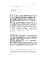
Ethernet port provided by the CPU of MP10 or MP11 board is connected to the LAN port
of the front panel of MP10/11. If 4SWM is mounted, the CPU Ethernet port is connected to
the Ethernet port of 4SWM, and another Ethernet port of 4SWM is connected to the LAN
port of the front panel. When 4SWM is mounted, automatically connected through relay in
MP10/11.
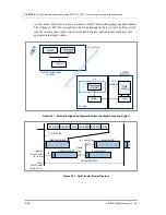
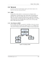
2.5.14.2 Board Block Diagram
The block diagram of the 4SWM module is as follows:
Figure 2.28 Block Diagram of 4SWM Module
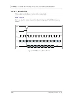
2.5.14.3 Main Features
Switch Controller (BCM5325E) Block
BCM5325E used as the switch controller of 4SWM is 6-port 10/100Base-T/TX switch
manufactured by Broadcom. BCM5325E includes Media Access Controller(MAC) that supports
six full duplex, and five 10 Base-T/100Base-TX fast Ethernet transceivers. In addition, it provides
one 10/100 MII interface and can be configured as the sixth port and connected to Reversed MII
of the processor. In 4SWM, it is used as the sixth port. If 4SWM is mounted, it switches with
LAN of MP10/11. Packet buffer memory and one address resolution engine are mounted
and non-blocking switch controller and Management Information Base(MIB) statistics
register are also included. 4SWM can be conveniently configured, and the L2 switch can be
also properly configured when the management function is used.
Main features are described as follows:
PoE Channel 1(Pos/Neg)
PoE Channel 2(Pos/Neg)
PoE Channel 3(Pos/Neg)
PoE Channel 4(Pos/Neg)
4 Channel
PoE
Manager
(PD64004)
4 Ports
Magnetic
Transformer
Modules
(H1164NLT)
Port 1
Port 2
Port 3
Port 4
Clock
Distributer
Clock
(25MHz OSC)
10/100 Switch
(BCM 5325E)
25 M
Clock
3.3 V 3.3 V
DC-DC Cov.
(MIC39151-1.
8BU)
25 M Clock
RD+ /-(1:4)
RD+ /-(1:4)
PHY
(BCM5241)
1 Port
Magnetic
Transformer
(H1102T)
RD+ /-(5)
1 Port
Magnetic
Transformer
(H1102T)
RD+ /-(5)
LAN In from
M82510
LAN Out
SMP(SCK, CS, DI, DO)
MII
25 M
Clock
3.3 V
1.8 V
3.3 V
-54 V
To Secondary Connector
To Primary Connector
Содержание OFFICESERV 7100
Страница 1: ...Ed 00 OfficeServ 7100 Service Manual ...
Страница 33: ...OfficeServ 7100 Service Manual SAMSUNG Electronics Co Ltd 1 15 ...
Страница 189: ...OfficeServ 7100 Service Manual SAMSUNG Electronics Co Ltd 5 3 Soldering Side ...
Страница 191: ...OfficeServ 7100 Service Manual SAMSUNG Electronics Co Ltd 5 5 5 3 4DLM Part Side Soldering Side ...
Страница 193: ...OfficeServ 7100 Service Manual SAMSUNG Electronics Co Ltd 5 7 5 5 4SLM Part Side Soldering Side ...
Страница 195: ...OfficeServ 7100 Service Manual SAMSUNG Electronics Co Ltd 5 9 5 7 TEPRI2 Board Part Side ...
Страница 197: ...OfficeServ 7100 Service Manual SAMSUNG Electronics Co Ltd 5 11 5 8 8COMBO Part Side ...
Страница 199: ...OfficeServ 7100 Service Manual SAMSUNG Electronics Co Ltd 5 13 5 9 16DLI2 Part Side ...
Страница 201: ...OfficeServ 7100 Service Manual SAMSUNG Electronics Co Ltd 5 15 5 10 MGI16 MGI32 Part Side ...
Страница 203: ...OfficeServ 7100 Service Manual SAMSUNG Electronics Co Ltd 5 17 5 11 16SLI2 16MWSLI Part Side ...
Страница 205: ...OfficeServ 7100 Service Manual SAMSUNG Electronics Co Ltd 5 19 5 12 8TRK Board Part Side ...
Страница 207: ...OfficeServ 7100 Service Manual SAMSUNG Electronics Co Ltd 5 21 5 13 PLIM Board Part Side ...
Страница 209: ...OfficeServ 7100 Service Manual SAMSUNG Electronics Co Ltd 5 23 5 14 Modem Part Side Soldering Side ...


