OfficeServ 7100 Service Manual
© SAMSUNG Electronics Co., Ltd.
XIII
LIST OF FIGURES
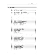
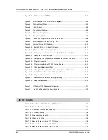
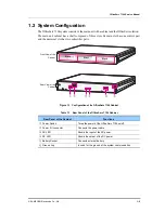
Figure 1.1 Configuration of the OfficeServ 7100 Cabinet ......................................................... 1-5
Figure 1.2 Loop Start C.O. line Signaling ................................................................................. 1-9
Figure 2.1 Physical Structure of the OfficeServ 7100 System ................................................. 2-1
Figure 2.2 Structure of the OfficeServ 7100 System Communication ...................................... 2-2
Figure 2.3 MP10/11 Board Block Diagram ............................................................................... 2-5
Figure 2.4 UNI Board Block Diagram ..................................................................................... 2-10
Figure 2.5 Block Diagram of the 4TRM Board ........................................................................ 2-12
Figure 2.6 Block Diagram of the DAA Chip ............................................................................ 2-13
Figure 2.7 Block Diagram of the QSLAC Part ........................................................................ 2-14
Figure 2.8 Block Diagram of the 8TRK Board ........................................................................ 2-15
Figure 2.9 Block Diagram of the C.O Line Interface Circuit ................................................... 2-16
Figure 2.10 Block Diagram of the 2BRM Board ..................................................................... 2-18
Figure 2.11 Layout between the 2BRM and UNI Boards ....................................................... 2-19
Figure 2.12 Block Diagram of the TEPRI2 Board ................................................................... 2-20
Figure 2.13 Block diagram of the 4SLM Module .................................................................... 2-24
Figure 2.14 Block Diagram of the 16SLI2/16MWSLI Boards ................................................. 2-27
Figure 2.15 8HYB/8COMBO DLI Block Diagram ................................................................... 2-29
Figure 2.16 8HYB/8COMBO SLI Block Diagram .................................................................... 2-30
Figure 2.17 4DLM Block Diagram ........................................................................................... 2-31
Figure 2.18 QDASL Block Diagram ........................................................................................ 2-32
Figure 2.19 QDMC Block Diagram ......................................................................................... 2-33
Figure 2.20 Block Diagram of the 8DLI Board ........................................................................ 2-34
Figure 2.21 Default Configuration Diagram Between the Digital Phone and System ............ 2-36
Figure 2.22 Data Transfer Format Diagram ............................................................................ 2-36
Figure 2.23 Block Diagram of the 16DLI Board ...................................................................... 2-38
Figure 2.24 Block Diagram of MGI64/MGI16 board ............................................................... 2-41
Figure 2.25 Block Diagram of the PLIM Board ....................................................................... 2-44
Figure 2.26 PoE Strap Option of PLIM Board ......................................................................... 2-46
Figure 2.27 4SWM Configuration Diagram ............................................................................. 2-47
Figure 2.28 Block Diagram of 4SWM Module ........................................................................ 2-48
Figure 2.29 Block Diagram of WBS24 BTS ............................................................................ 2-51
Figure 2.30 Phone System Connection Diagram ................................................................... 2-52
Figure 2.31 Modem Board Block Diagram ............................................................................. 2-55
Figure 2.32 PCM Interface of Modem Board .......................................................................... 2-56
Figure 2.33 Block Diagram of DPIM ....................................................................................... 2-57
Figure 2.34 Block Diagram of Door Phone ............................................................................. 2-58
Содержание OFFICESERV 7100
Страница 1: ...Ed 00 OfficeServ 7100 Service Manual ...
Страница 33: ...OfficeServ 7100 Service Manual SAMSUNG Electronics Co Ltd 1 15 ...
Страница 189: ...OfficeServ 7100 Service Manual SAMSUNG Electronics Co Ltd 5 3 Soldering Side ...
Страница 191: ...OfficeServ 7100 Service Manual SAMSUNG Electronics Co Ltd 5 5 5 3 4DLM Part Side Soldering Side ...
Страница 193: ...OfficeServ 7100 Service Manual SAMSUNG Electronics Co Ltd 5 7 5 5 4SLM Part Side Soldering Side ...
Страница 195: ...OfficeServ 7100 Service Manual SAMSUNG Electronics Co Ltd 5 9 5 7 TEPRI2 Board Part Side ...
Страница 197: ...OfficeServ 7100 Service Manual SAMSUNG Electronics Co Ltd 5 11 5 8 8COMBO Part Side ...
Страница 199: ...OfficeServ 7100 Service Manual SAMSUNG Electronics Co Ltd 5 13 5 9 16DLI2 Part Side ...
Страница 201: ...OfficeServ 7100 Service Manual SAMSUNG Electronics Co Ltd 5 15 5 10 MGI16 MGI32 Part Side ...
Страница 203: ...OfficeServ 7100 Service Manual SAMSUNG Electronics Co Ltd 5 17 5 11 16SLI2 16MWSLI Part Side ...
Страница 205: ...OfficeServ 7100 Service Manual SAMSUNG Electronics Co Ltd 5 19 5 12 8TRK Board Part Side ...
Страница 207: ...OfficeServ 7100 Service Manual SAMSUNG Electronics Co Ltd 5 21 5 13 PLIM Board Part Side ...
Страница 209: ...OfficeServ 7100 Service Manual SAMSUNG Electronics Co Ltd 5 23 5 14 Modem Part Side Soldering Side ...


