


Error! Use the Home tab to apply
제목
7,
제목
7_
목차
to the text that you want to appear here.
XIV
© SAMSUNG Electronics Co., Ltd.
Figure 2.35 Pin Connection of DPIM ...................................................................................... 2-59
Figure 4.1 Initial Window of the Smart Media Program ............................................................ 4-2
Figure 4.2 [Format Menu] Window ........................................................................................... 4-3
Figure 4.3 SMC Format ............................................................................................................ 4-4
Figure 4.4 [Copy Menu] Window .............................................................................................. 4-5
Figure 4.5 [Directory Menu] Window ........................................................................................ 4-6
Figure 4.6 [Copy Menu] Window .............................................................................................. 4-7
Figure 4.7 Connection Diagram of the PC and the Board ....................................................... 4-8
Figure 4.8 Initial Window of the ispVM Program ...................................................................... 4-9
Figure 4.9 [LatticePRO ver 0.1] Window ................................................................................ 4-10
Figure 4.10 [LatticePRO ver 0.1-Chain1] Window .................................................................. 4-11
Figure 4.11 [Advanced Processing Options] Window ............................................................. 4-11
Figure 4.12 Designating the Part Name on the [JTAG Part Properties] Window .................. 4-12
Figure 4.13 Setting the CPLD Part Type ................................................................................ 4-12
Figure 4.14 Designating the Programming Mode and the JEDEC File Path ......................... 4-13
Figure 4.15 Program Execution .............................................................................................. 4-14
Figure 4.16 Programming for the MP10/11 Option Board ...................................................... 4-15
Figure 4.17 Changing Information of Part1 ............................................................................ 4-16
Figure 4.18 Viewing the Chain File When One Option Board Is Mounted............................. 4-16
Figure 4.19 Initial Window of the Altera MAX+plus II Program .............................................. 4-17
Figure 4.20 Program File Selection ........................................................................................ 4-18
Figure 4.21 Selection of the Data File for Programming ........................................................ 4-18
Figure 4.22 Data File Download ............................................................................................. 4-19
Figure 7.1 OfficeServ 7100 Disassembly Diagram .................................................................. 7-1
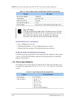
Figure 7.2 Front/Rear Panels of the Power Module ................................................................. 7-2
LIST OF TABLES
Table 1.1 Rear Panel of the OfficeServ 7100 Cabinet ............................................................. 1-5
Table 1.2 Boards Mountable to Slots ........................................................................................ 1-6
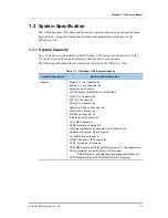
Table 1.3 OfficeServ 7100 System Capacity ............................................................................ 1-7
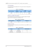
Table 1.4 C.O. line Capacity ..................................................................................................... 1-8
Table 1.5 Extension Line Capacity............................................................................................ 1-8
Table 1.6 Channels by Slots ..................................................................................................... 1-8
Table 1.7 Electric Characteristics of T1 C.O. line ..................................................................... 1-9
Table 1.8 Electric Characteristics of E1 C.O. line ................................................................... 1-10
Table 1.9 Electric Characteristics of BRI C.O. line ................................................................. 1-10
Содержание OFFICESERV 7100
Страница 1: ...Ed 00 OfficeServ 7100 Service Manual ...
Страница 33: ...OfficeServ 7100 Service Manual SAMSUNG Electronics Co Ltd 1 15 ...
Страница 189: ...OfficeServ 7100 Service Manual SAMSUNG Electronics Co Ltd 5 3 Soldering Side ...
Страница 191: ...OfficeServ 7100 Service Manual SAMSUNG Electronics Co Ltd 5 5 5 3 4DLM Part Side Soldering Side ...
Страница 193: ...OfficeServ 7100 Service Manual SAMSUNG Electronics Co Ltd 5 7 5 5 4SLM Part Side Soldering Side ...
Страница 195: ...OfficeServ 7100 Service Manual SAMSUNG Electronics Co Ltd 5 9 5 7 TEPRI2 Board Part Side ...
Страница 197: ...OfficeServ 7100 Service Manual SAMSUNG Electronics Co Ltd 5 11 5 8 8COMBO Part Side ...
Страница 199: ...OfficeServ 7100 Service Manual SAMSUNG Electronics Co Ltd 5 13 5 9 16DLI2 Part Side ...
Страница 201: ...OfficeServ 7100 Service Manual SAMSUNG Electronics Co Ltd 5 15 5 10 MGI16 MGI32 Part Side ...
Страница 203: ...OfficeServ 7100 Service Manual SAMSUNG Electronics Co Ltd 5 17 5 11 16SLI2 16MWSLI Part Side ...
Страница 205: ...OfficeServ 7100 Service Manual SAMSUNG Electronics Co Ltd 5 19 5 12 8TRK Board Part Side ...
Страница 207: ...OfficeServ 7100 Service Manual SAMSUNG Electronics Co Ltd 5 21 5 13 PLIM Board Part Side ...
Страница 209: ...OfficeServ 7100 Service Manual SAMSUNG Electronics Co Ltd 5 23 5 14 Modem Part Side Soldering Side ...