CHAPTER
12
.
Error! Use the Home tab to apply
제목
1,
장
제목
1 to the text that you want to appear here.
2-16
© SAMSUNG Electronics Co., Ltd.
2.5.3.2 Major features
The major features of the 8TRK module is as follows:
Structure
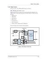
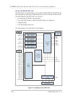
The following figure shows the block diagram of the C.O line interface circuit:
Figure 2.9 Block Diagram of the C.O Line Interface Circuit
The above circuit consists of DC current by-pass circuit, matching trans, balance network, hybrid
circuit, channel assign timing control, PCM CODEC, digital gain circuit logic to transmit/receive
voice frequency(300~3400 Hz) to/from the C.O. line. In addition, it constructs a separate DC by-
pass circuit to miniaturize a transformer for voice path.
This circuit embeds the HOS and Ring Signal Detection circuits and uses the TSAC Enable
signal generated inside TMC to control the highway buffer(74ABT125) of the time slot
assign circuit. The Hybrid circuit for impedance matching is designed as the Hybrid circuit
for the line impedance of 600
Ω
.
Voice Sending/Receiving Part
This part performs the surge protection function via the primary protection to withstand the
high voltage supplied between tip lead and ring lead. In addition, the part constructs the
tertiary protection circuit by using a zener diode inside the impedance matching circuit on
the transformer secondary side. The bi-directional voice received from the
C.O board is
separated from the line loop feeding power and entered to the voices signal transformer
through the coupling capacitor.
Relay
Loop
Rectifier
&
DC By-pass
Ring
Detection
Loop
Detection
Conversion
4W to 2W
Hybrid
Balance
Circuit
Base
Gain
Setup
Circuit
Impedance
Matching
Circuit
Low
Pass
Filter
Low
Pass
Filter
CODEC
Protection
Line
Port control circuit
(Relay Drive Circuit)
Dial Pulse Generation
Circuit
Port
Status
Read
Circuit
Time Slot
Assignment
Automatic Gain
Controller(A.G.C)
Buffer
Circuit
Data & Address Bus
Control Bus
Highway Signal
TMC(STL7053)
Tip
Ring
Содержание OFFICESERV 7100
Страница 1: ...Ed 00 OfficeServ 7100 Service Manual ...
Страница 33: ...OfficeServ 7100 Service Manual SAMSUNG Electronics Co Ltd 1 15 ...
Страница 189: ...OfficeServ 7100 Service Manual SAMSUNG Electronics Co Ltd 5 3 Soldering Side ...
Страница 191: ...OfficeServ 7100 Service Manual SAMSUNG Electronics Co Ltd 5 5 5 3 4DLM Part Side Soldering Side ...
Страница 193: ...OfficeServ 7100 Service Manual SAMSUNG Electronics Co Ltd 5 7 5 5 4SLM Part Side Soldering Side ...
Страница 195: ...OfficeServ 7100 Service Manual SAMSUNG Electronics Co Ltd 5 9 5 7 TEPRI2 Board Part Side ...
Страница 197: ...OfficeServ 7100 Service Manual SAMSUNG Electronics Co Ltd 5 11 5 8 8COMBO Part Side ...
Страница 199: ...OfficeServ 7100 Service Manual SAMSUNG Electronics Co Ltd 5 13 5 9 16DLI2 Part Side ...
Страница 201: ...OfficeServ 7100 Service Manual SAMSUNG Electronics Co Ltd 5 15 5 10 MGI16 MGI32 Part Side ...
Страница 203: ...OfficeServ 7100 Service Manual SAMSUNG Electronics Co Ltd 5 17 5 11 16SLI2 16MWSLI Part Side ...
Страница 205: ...OfficeServ 7100 Service Manual SAMSUNG Electronics Co Ltd 5 19 5 12 8TRK Board Part Side ...
Страница 207: ...OfficeServ 7100 Service Manual SAMSUNG Electronics Co Ltd 5 21 5 13 PLIM Board Part Side ...
Страница 209: ...OfficeServ 7100 Service Manual SAMSUNG Electronics Co Ltd 5 23 5 14 Modem Part Side Soldering Side ...


