11
•
The
[0]-[9]
dial buttons are used to directly choose a menu, or sub menu
options.
•
The
[ENTER]
button in the navigation button assembly is used when saving a
modification.
•
The
[MENU]
button in the navigation button assembly is used to to display
the IP Setup Main Menu.
•
The
[END]
button in the navigation button assembly is used when canceling
or editing the modification, or existing programming.
•
The
[CANCEL]
button in the navigation button assembly is used to go back to
the previous screen or to delete the last digit of a displayed option value.
MENU STRUCTURE
The IP SETUP MENU is configured as follows:
1.
SYSTEM EASY WIZARD
This option will guide you through setting up all required parameters for con-
necting the ITP keyset to your system.
2.
SYSTEM INFORMATION
1.
Version Info: Provides boot rom, software, DSP, and hardware version
information.
2.
Network Info: Displays network mode, IP address of phone, network, and
gateway information.
3.
Netmask
4.
Gateway
Note that items 2 to 4 are only displayed when setting Manual IP.
3.
NETWORK SETUP
This menu allows you to individually setup the same parameters found in the
Easy Wizard.
4.
LOAD & UPGRADE SETUP
1.
Upgrade TFTP Server: The IP address of the TFTP server containing the ITP
software.
2.
Upgrade Start: Starts the ITP software upgrade process.
5.
SYSTEM SERVER SETUP
1.
Server IP Address: The MCP’s IP address.
2.
Server ID: The ID assigned to your ITP (see your phone administrator for
this information).
3.
Server Pass: The password assigned to your ITP (see your phone adminis-
trator for this information).
ITP-5112L SETUP
INITIALIZING THE ITP-5112L
Initially the ITP-5112L IP keyset will need to be setup to operate within the users
network.The Setup Menu is also used to make changes to the keyset, in the event
that the system information should change. The option chosen via scroll button
will be highlighted.
The station numbers will be automatically set by the OfficeServ 100, the
OfficeServ 500, or the OfficeServ 7000 Series systems once the necessary infor-
mation has been entered into the IP keyset. Enter ID and password of the server,
as described below to register the phone.
See your system administrator for specific Network and Server addresses. The
addresses necessary to set up the ITP-5112L are:
•
IP Address of Station
•
Network Gateway Address
•
IP Address of System’s MCP
•
User ID
•
Password
IP SETUP MENU
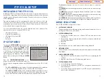
To get to the
SETUP MODE
unplug the power cord from the ITP. Press and hold
the
MENU
button while you plug power back
into the phone. Release the
MENU
button
when you see the
SETUP SCREEN
. If you have
a PoE (Power over Ethernet) connection, the
same procedure can be done by unplugging
and plugging the Ethernet cable into the
phone while pressing and holding the
MENU
button.
Once the
CONFIGURATION MENU
is dis-
played, you can move to each menu in the Set
Up by using the navigation buttons and
[1]-[9]
dial buttons of the ITP-5112L IP
phone.
•
The
UP
and
DOWN
directions buttons in the navigation button assembly are
used to move the highlighted bar up or down to the desired option.
•
The
LEFT
and
RIGHT
buttons in the navigation button assembly are used to
move the highlighted bar left or right, to the desired option, move to a sub
menu and if a menu is at the last line, that menu option will be executed.
Configuration
*1.System Easy Wizard
2.System Information
3.Network Setup
4.Load & Upgrade Setup
5.System Server Setup
6.Factory Reset
7.Reboot
10
Table of Contents
ITP-5112L
Home Page


