


23
English
Instal
lation
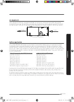
Power supply connections
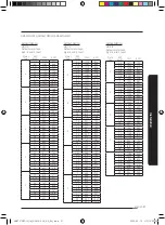
If the air handler has been installed prior to installing the electric heaters or if an older unit is being replaced, the supply
power wires must be checked to make sure the wires are the proper sizes to handle the current load for the heaters. Refer
to table below for correct wire size. If the supply power wire size is incorrect, new wires will need to be installed. Follow the
instructions “Power Supply Wiring” on page 18 of these instructions for proper installation.
ELECTRICAL DATA
Indoor Unit
Model
Electric Heater Data
Minimum Circuit
Ampacity (MCA)
Maximum Overcurrent
Protection (MOCP)
Minimum Wire Size
(AWG)
Short-Circuit
Current Rating
Circuit
Qty.
Kw (2)
Amps
208V
Amps
208V
Amps
240V
Amps
240V 208V 208V 240V 240V
208V
(3,4)
208V
(3,4)
240V
(3,4)
240V
(3,4)
Circuit 1
Circuit 2
"SCCR"
75°C /
90°C 60°C
75°C /
90°C 60°C
kA rms
symmetrical
V
maximum
Circuit
1
Circuit
2
Circuit
1
Circuit
2
Circuit
1
Circuit
2
Circuit
1
Circuit
2
Circuit
1
Circuit
2
Circuit
1
Circuit
2
SMALL CABINET-NOMINAL1.0, 1.5 & 2.0 TONS (0 To 5 Kw)
AM012TNZDCH
1
0
0
-
0
-
0.90
-
0.90
-
10.0
-
10.0
-
#14
#14
-
-
n/a
n/a
1
3
10.90
-
12.50
-
13.63
-
15.63
-
15.0
-
20.0
-
#12
#12
-
-
n/a
n/a
AM018TNZDCH
AM024TNZDCH
0
0
0
-
0
-
0.90
-
0.90
-
10.0
-
10.0
-
#14
#14
-
-
n/a
n/a
1
3
10.90
-
12.50
-
13.63
-
15.63
-
15.0
-
20.0
-
#12
#12
-
-
n/a
n/a
1
5
18.03
-
20.83
-
23.26
-
26.76
-
30.0
-
30.0
-
#10
#10
-
-
n/a
n/a
MEDIUM CABINET-NOMINAL 2.5, 3.0 TONS (0 To 10 Kw)
AM030TNZDCH
AM036TNZDCH
1
0
-
-
2.08
-
2.08
-
10.0
-
10.0
-
#14
#14
-
-
n/a
n/a
1
5
18.03
-
20.83
-
24.20
-
27.70
-
30.0
-
30.0
-
#10
#10
-
-
n/a
n/a
1
10
36.06
-
41.67
-
46.73
-
53.74
-
50.0
-
60.0
-
#6
#4
-
-
n/a
n/a
LARGE CABINET-NOMINAL 4.0, 4.5, 5.0, 6.0 TONS (0 To 20 Kw)
AM048TNZDCH
1
0
-
-
2
-
2.6
-
15.06
-
15.0
-
#14
#14
-
-
n/a
n/a
1
5
18.0
-
20.8
-
24.6
-
26.0
-
30.0
-
30.0
-
#10
#10
-
-
n/a
n/a
1
10
36.1
-
41.7
-
45.1
-
52.1
-
50.0
-
60.0
-
#6
#4
-
-
n/a
n/a
AM054TNZDCH
AM060TNZDCH
1
0
-
-
2
-
2.6
-
15.06
-
15.0
-
#14
#14
-
-
n/a
n/a
1
5
18.0
-
20.8
-
24.6
-
26.0
-
30.0
-
30.0
-
#10
#10
-
-
n/a
n/a
1
10
36.1
-
41.7
-
45.1
-
52.1
-
50.0
-
60.0
-
#6
#4
-
-
n/a
n/a
2
15
18.0
36.1
20.8
41.7
24.6
47.2
28.1
54.2 30.0 50.0 30.0 60.0
#6
#4
#10
#10
5
240
AM072TNZDCH
1
0
-
-
7
-
7.2
-
15.02
-
15.0
-
#14
#14
-
-
n/a
n/a
1
5
18.0
-
20.8
-
28.3
-
26.0
-
30.0
-
30.0
-
#10
#10
-
-
n/a
n/a
1
10
36.1
-
41.7
-
45.1
-
52.1
-
50.0
-
60.0
-
#6
#4
-
-
n/a
n/a
2
15
18.0
36.1
20.8
41.7
28.2 50.8
31.7
57.8
30.0 60.0 35.0 60.0
#6
#4
#10
#10
5
240
2
20
36.1
36.1
41.7
41.7
50.8 50.8
57.8
57.8
60.0 60.0 60.0 60.0
#6
#4
#6
#4
5
240
1. Rated Motor Amps (at DOE External Static Rating Point)
2. Nominal Kw At 240V (Derate 25% For 208V)
3. Fuse or HACR Breaker
4. Maximum Overcurrent Device, Overcurrent Protection Installed On Breaker Models Are Sized Per MCA
•
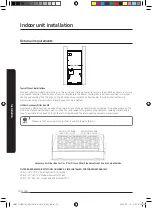
To prevent damage, carefully insert the electric heating assembly through the rectangular opening in the front of the
discharge opening so the heat element support rod is seated into the hole on the back side of the discharge opening.
•
After installing the electric heater, a one inch clearance must be maintained on all sides of the supply air duct and/or
plenum for a minimum of thirty six inches from the air handler discharge opening.
AM072TNZDCH_IM_DVM V-AHU_AA_EN_.indd 23
2020-02-14 오전 10:33:34
Содержание AM0 SERIES
Страница 45: ...45 English Appendix Memo AM072TNZDCH_IM_DVM V AHU_AA_EN_ indd 45 2020 02 14 오전 10 33 41 ...
Страница 46: ...AM072TNZDCH_IM_DVM V AHU_AA_EN_ indd 46 2020 02 14 오전 10 33 41 ...
Страница 91: ...45 Français Annexe Note AM072TNZDCH_IM_DVM V AHU_AA_FR_ indd 45 2020 02 14 오전 10 35 49 ...
Страница 92: ...AM072TNZDCH_IM_DVM V AHU_AA_FR_ indd 46 2020 02 14 오전 10 35 49 ...


