


5.2 Establishing the connection
– Route and secure the lines in the actuator
such that they are protected from moving or
rotating parts and cannot be damaged
when removing or replacing the cover.
5.4
Start-up
The following applies for a first working simu-
lation:
– Use handwheel to move actuator stem to-
wards the center of the travel.
– Connect grounding contactor to grounding
contactor clamp .
– Connect supply voltage.
A.C. motors
N
=
^
clamp
1
L
=
^
clamp
3
The actuator stem extends from the actuator
and moves to
"CLOSED"
position (closes).
N
=
^
clamp
1
L
=
^
clamp
2
The actuator stem retracts into the actuator
and moves to
"OPEN"
position (opens).
Three-phase a.c. drive motors
External reversing contactors should be used.
L
1
=
^
clamp
1
;
L
2
=
^
clamp
2
;
L
3
=
^
clamp
3
Switch on the supply voltage, thus issuing the
short-term command "OPEN/CLOSED" .
– Check, whether the actuator stem moves in
the right direction.
– If the actuator stem does not move in the
right direction, switch motor connections 2
and 3, and repeat test.
!
!
WARNING!
The actuators must only be adjusted
electrically or manually within the
given travel.
If you adjust the travel to a value ex-
ceeding the given values, the actuator
may be damaged!
NOTE!
For the electrical connection, refer to the circuit
diagram displayed inside the lid!
When installing electric lines, you are required to
observe the regulations governing power plant
installations!
Especially with 24-V-actuators, you should make
sure that the line cross sections are sufficiently
sized and that there is enough reserve capacity
left in the transformer.
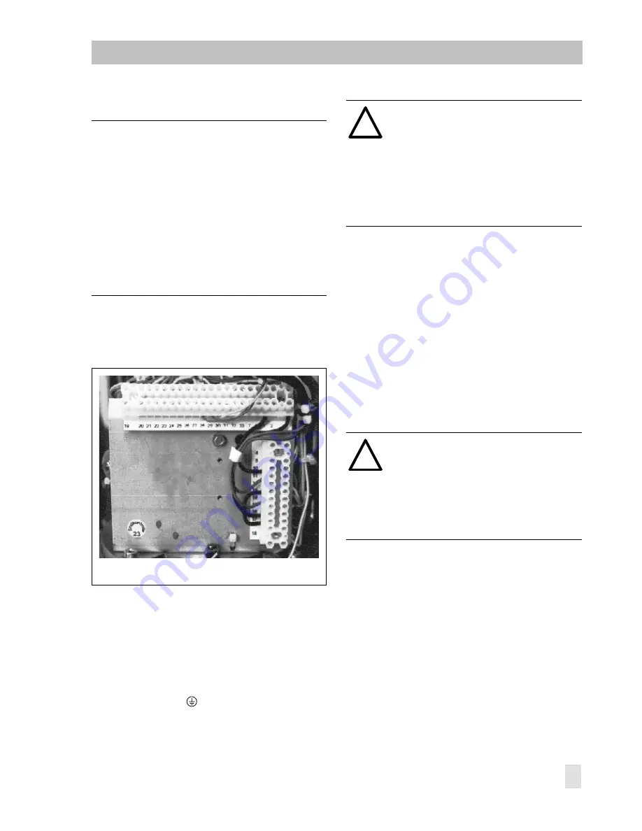
Fig. 10
⋅
Terminal blocks for electrical connection
WARNING!
With the wrong direction of rotation,
even correctly wired torque switches
cannot switch off the motor. When
"testing" the operating direction, use
short-term commands only.
$