


6-4
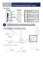
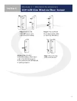
Module 2 – Wireless Accessories
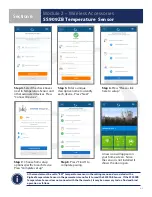
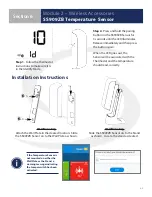
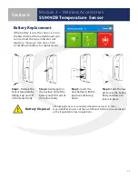
SS909ZB Temperature Sensor
Section 6
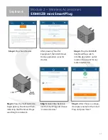
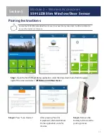
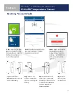
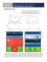
Step 1.
Follow the thermostat
instructions to make sure it is
in the Identify Mode .
Step 2.
Press and hold the pairing
button on the SS909ZB Sensor for
3 seconds until the LED Illuminates .
Release immediately and then press
the button again .
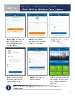
When the LED goes out, the
Sensor will be associated with the
Thermostat and the temperature
should read, correctly .
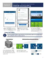
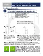
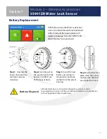
Wall Mounting
Attach the Wall Plate in the desired location . Slide
the SS909ZB Sensor on to the Wall Plate as shown .
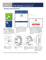
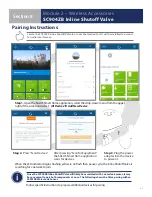
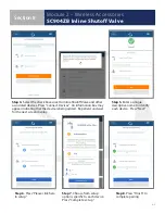
Installation Instructions
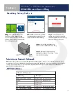
Wall Mounting
Slide the SS909ZB Sensor on to the Stand
as shown . Locate the stand as desired .
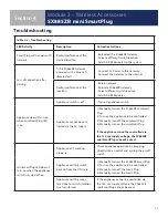
If the Temperature Sensor is
not mounted on either the
Wall Plate or the Stand, a
warning message indicating
the tamper switch has been
activated.


