


- 19 -
7.9.- Computer connections, communication ports and software.
•
The communication lines (interface) constitute a safety circuit of very low voltage. To preserve this quality, they should
be installed separated from other lines with dangerous voltages (like distribution lines of energy).
• The equipment has different communication channels, through them it is possible to communicate the
UPS
with the environment.
Through the series port RS-232 or the USB port can be done a direct connection with your IT system, not being possible to use
both ports at the same time.
Optionally there are two interface cards, not being possible to use both at the same time. One is the SNMP/WEB card for the
management and supervision through the local network or internet. And the second one is the 5-dry contact AS/400 card.
Both interface cards can be used together with the RS-232 or USB ports.
7.9.1.- Connector (C7), optocoupler interface and RS-232.
• The interface enables a dialogue between the
UPS
and the exterior world. Through optocouplers it receives information on:
Status of the mains and End of back up time. The same connector
(C7)
holds the signals of the RS-232 and a «Shutdown»
input (between pins 3 and 5) that allows the
UPS
to be able to be turned off when there is a voltage of 12 V DC for more than
5 sec., as long as there is no mains.
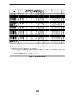
In the table 2 is showed the pin-out of the port and their
functions.
Do not apply higher values than 24V DC 50mA to the pins.
• The
UPS
is supplied with the interlink cable between the
RS-232 and the computer and «UPSMON» software to be
installed by the user. Once the physical connection has
been made with the cable between the
UPS
and the com-
puter, and the software has been installed, the operation
system will be intelligent, giving the full protection capac-
ity to the supplied critical loads when the complete instal-
lation is working.
The connection of the interface between the
UPS
and the computer is not implicit to the operating of both units.
The communication with the RS-232 port, will be done with a specific cable for this channel and with a maximum
number of 6 wires.
Do not use standard RS-232 cables of 9 wires
.
5
1
9
6
Fig. 4. Interface RS-232, connector (C7).
Table 2. Pin-out of the SUB-D9 connector, optocoupler and RS-232 interfaces.
Pin Nr.
Signal name.
UPS direction.
Function
2
TxD
Output.
TxD Output.
3
RxD
Input
RxD / Shutdown.
5
Common.
Output.
Common.
6
CTS
Output.
AC input failure.
8
DCD
Output.
Low battery voltage.
9
RI
Output.
Power 8 to -24V DC.
Содержание SLC Link Series
Страница 1: ...EK708A01 SLC LINK Service Manual...
Страница 64: ...63...
Страница 65: ...08460 Palautordera Tel 34 93 848 24 00 sat salicru com salicru com...
Страница 99: ...34...
Страница 138: ...73...
Страница 139: ...74...
Страница 140: ...75...
Страница 141: ...08460 Palautordera Tel 34 93 848 24 00 sat salicru com salicru com...