


18
SALICRU
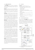
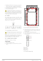
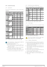
Fig. 14
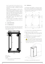
shows, byway of example, a single-line diagram of the
device with three-phase input and output.
All modules in the cabinet are structured according to the same
criteria, terminals for the power supply of the PFC rectifier and
independent static bypass, and input, output, static bypass
and manual bypass disconnectors. However, unless otherwise
requested, for separate networks originally from the factory,
the terminals of the phases of both blocks are connected by
means of strips to provide a single common input.
When separate power supplies are required, it is
obligatory to remove the strips between the phases of
both blocks before connecting the power cables, leaving the
connection strip of the neutral terminals.
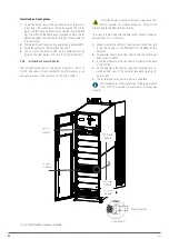
4.3.2.1. Power modules (PM).
Power modules are the basic core of the entire
SLC ADAPT
system. Apart from the static bypass block and LCD touch
screen, each power module contains all of the converters and
functionalities of a traditional UPS. Since this device consists
of a number of variable modules depending on the cabinet
used, a multi-parallel system is obtained with the behaviour
equivalent to that of a single mono-bloc UPS and the advan-
tages of a modular UPS.
The system supplies power to the critical load (such as com-
munication and data processing equipment) with uninterrupted
high quality AC power. The power supplied by the unit is stable,
without voltage and/or frequency variations and free from
other disturbances such as cuts or micro-cuts, sine wave al-
terations, electrical noise, anomalies commonly present in the
commercial AC network.
This is achieved through the double-conversion high frequency
Pulse Width Modulation (PWM), in combination with a digital
control based on a Digital Signal Processor (DSP), which pro-
vides high reliability and availability.
As can be seen in
Fig. 14
, the AC power supplied to the UPS
input is converted into DC voltage. This voltage supplies a con-
verter that transforms the voltage type from DC to AC, clean of
disturbances and variations of the AC input mains. If this fails,
the PFC rectifier changes the input source of the AC mains to
that of the batteries, powering in the same way through the
output of the UPS to the load for a limited time, that of the
backup determined by the battery pack.
4.3.2.1.1. Available power ratings.
The SLC ADAPT series has two different power modules, 30
and 50 kVA, as can be seen in Fig. 2, Fig. 4, Fig. 10 and Fig. 12.
4.3.2.2. Static bypass.
Static transfer switch.
In the event of inverter failure, overload or overtemperature,
the voltage connected to the static bypass line can supply
power to the load connected to the UPS output.
The static bypass module identified in
Fig. 14
contains the
power management and control circuits that allow the most
optimum decision in each scenario to be made, in order to se-
lect the most favourable power to the critical load connected
to the output of the UPS, either from the inverter or from the
static bypass itself.
During normal system operation, the load is connected to the
inverter and in case of overload or failure, it will automatically
transfer to the static bypass line. In order to provide a clean
transfer (without interruption) between the inverter output and
the bypass line, they must be fully synchronized during normal
operation. This is achieved through real-time digital control of
the inverter, so that the frequency of the inverter follows the
frequency of the bypass line if the bypass is within the range of
acceptable frequencies.
In addition, a Manual Bypass, which is very useful during periods
of maintenance or failure, is included and allows continuous
powering of the critical load while the UPS is out of service.
When the UPS is operating in bypass mode (over static
bypass), connected devices are not protected against
power cuts or micro-cuts, overvoltages, voltage and/or fre-
quency variations as they are powered directly from the AC
mains.
4.3.2.3. Extra charger modules for 180 and 300 kVA devices.
The smart charging module is designed to supply the necessary
charging current for long backup applications. The module is hot
swappable and has the same size and appearance of any power
module, supplying an adjustable current of between 0 and 50 A.
On the front, they have a high resolution LCD where the user
can monitor the different load parameters in real time.
The modules are designed to be inserted in 6- and 10-slot
cabinets with only 30 kVA modules - 180 and 300 kVA devices
- and can be inserted in the necessary number to meet battery
charging needs.
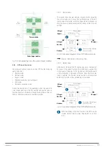
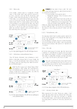
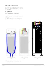
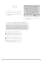
4.3.2.3.1. Wiring diagram.
As can be seen in the diagram in Fig. 15, the charger modules
are connected in parallel to the power modules. The total cur-
rent of the system is the sum of the current supplied by the
power modules and the charger modules.
Содержание SLC ADAPT Series
Страница 1: ...SLC serie ADAPT 180 300 y 500 kVA UNINTERRUPTIBLE POWER SUPPLY UPS USER S MANUAL...
Страница 10: ...10 SALICRU Fig 6 Front and rear view of 10 slot cabinet 300 kVA 200 kVA at 3x208 V with closed doors...
Страница 12: ...12 SALICRU Fig 8 Front view of 10 slot cabinet 500 kVA 300 kVA at 3x208 V with closed doors...
Страница 64: ...64 SALICRU...
Страница 65: ...65 SLC ADAPT UNINTERRUPTIBLE POWER SUPPLY UPS USER S MANUAL...


