background image

S.P. RADIO A/S

AALBORG

DENMARK

TECHNICAL MANUAL

FOR

COMPACT VHF RT2047/D

Содержание RT2047

Страница 1: ...S P RADIO A S AALBORG DENMARK TECHNICAL MANUAL FOR COMPACT VHF RT2047 D ...

Страница 2: ......

Страница 3: ...ION HINTS 2 1 2 2 MOUNTING POSSIBILITIES 2 2 2 3 DIMENSIONS AND DRILLING PLAN 2 4 2 4 HANDSET 2 9 2 5 MICROTELEPHONE CONNECTOR 2 9 2 6 POWER SUPPLY 2 9 2 7 POWER AND EXT LOUDSPEAKER CONNECTOR 2 10 2 8 ANTENNAS 2 10 2 9 SPECIAL OPTIONS 2 10 2 10 REAR VIEW OF VHF RT2047 2 11 2 11 STANDARD FREQUENCY TABLE 2 12 ...

Страница 4: ...AL INSTALLATION WITH 2 MICROTELEPHONES 2 35 2 13 SPECIAL INSTALLATION WITH 3 MICROTELEPHONES 2 36 2 14 MECHANICAL DIMENSIONS FOR HANDSET 2 37 2 15 DC POWER SUPPLY N418 2 39 2 16 N420 24V 12V REGULATOR 2 42 3 MECHANICAL DISASSEMBLING AND MODULE LOCATION 3 1 3 1 MECHANICAL DISASSEMBLING 3 1 3 2 MODULE LOCATION 3 3 4 SERVICE 4 1 4 1 MAINTENANCE 4 1 4 2 ADJUSTMENT INSTRUCTIONS 4 1 4 3 PROPOSAL FOR NEC...

Страница 5: ...RT2047 DSC PART I CONTENTS 1 GENERAL INFORMATION 1 1 1 1 INTRODUCTION 1 1 ...

Страница 6: ......

Страница 7: ...onditions experienced in small semi open boats Its compact weather proof construction ensures a degree of resistance to sea spray The printed circuits which have made possible a combination of compactness and exceptional performance are coated with a special moisture repellent lacquer In the design of this VHF radiotelephone S P Radio have taken into account all conditions it will be exposed to in...

Страница 8: ......

Страница 9: ...NG POSSIBILITIES 2 2 2 3 DIMENSIONS AND DRILLING PLAN 2 4 2 4 HANDSET 2 9 2 5 MICROTELEPHONE CONNECTOR 2 9 2 6 POWER SUPPLY 2 9 2 7 POWER AND EXT LOUDSPEAKER CONNECTOR 2 10 2 8 ANTENNAS 2 10 2 9 SPECIAL OPTIONS 2 10 2 10 REAR VIEW OF VHF RT2047 2 11 2 11 STANDARD FREQUENCY TABLE 2 12 ...

Страница 10: ......

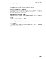
Страница 11: ...e it will be at the disposal of trained personal in their service facilities IN WHAT WAY TO INSTALL THE VHF RT2047 In section 2 2 MOUNTING POSSIBILITIES there s installation instructions for the VHF RT2047 as an independent unit or in combination with other units in the Compact 2000 programme HANDSET Installation of handset see section 2 4 HANDSET EXTERNAL LOUDSPEAKER An external loudspeaker 4 8 o...

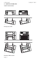
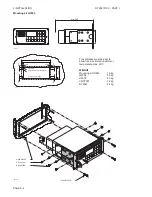
Страница 12: ...2 INSTALLATION RT2047 DSC PART I PAGE 2 2 2 2 MOUNTING POSSIBILITIES TABLETOP AND DECKHEAD 24889 Mounting bracket H2055 24890 Mounting kit H2068 and H2055 ...

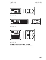
Страница 13: ... PART I PAGE 2 3 BULKHEAD AND CONSOLE 24892 Mounting kit H2063 24893 Mounting kit H2062 24891 Mounting kit H2064 IN CONJUNCTION WITH OTHER S P RADIO EQUIPMENT Look up the INSTALLATION section for the S P RADIO unit in question ...

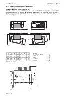
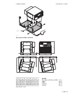
Страница 14: ...ack or assembly of all units in the Compact programme on the bulkhead see special information concerning installation of the Compact programme 132 132 225 115 132 min 117 F E D B C 48 A 24894A α A B C D E F 0 130 48 117 130 48 117 4 8 142 48 117 146 53 117 9 6 155 48 118 163 59 116 14 4 167 45 133 178 65 113 WEIGHT Mounting kit H2055 1 5 kg H2054 5 5 kg H2074 4 0 kg CRY2001 3 2 kg RT2047 5 2 kg Di...

Страница 15: ... H2055 132 132 48 132 225 215 D A B C F E 117 24895 α A B C D E F 0 230 67 117 230 67 117 4 8 243 67 129 245 72 117 9 6 255 65 142 262 78 115 14 4 265 62 155 270 89 112 WEIGHT Mounting kit H2068 and H2055 1 5 kg H2054 5 5 kg H2074 4 0 kg CRY2001 3 2 kg RT2047 5 2 kg Dimensions in mm ...

Страница 16: ...6mm 4 stk 3 5mm uns for M3 DIN 963 Cutting out 231x100mm 253mm 240mm 100mm 113mm 27444A Free distance must be kept to allow free air circulation ambient temperature max 40 C WEIGHT Mounting kit H2063 1 0 kg H2054 5 5 kg H2074 4 0 kg CRY2001 3 2 kg RT2047 5 2 kg 4 pcs M3x30 4 pcs cover 8 pcs M5x8 4 pcs M5x30 24770 ...

Страница 17: ...IN 963 Cutting out 231x200mm 200mm 208mm 221mm 20mm 20mm 4 5mm 4 5mm 20mm 20mm 253 00 27447A Free distance must be kept to allow free air circulation ambient temperature max 40 C WEIGHT Mounting kit H2064 1 5 kg H2054 5 5 kg H2074 4 0 kg CRY2001 3 2 kg RT2047 5 2 kg 4 pcs M3x30 8 pcs cover 16 pcs M5x8 4 pcs M5x30 24899 ...

Страница 18: ... 451x100mm 473mm 460mm 6mm 6mm 10mm 10mm 2 stk ø3mm 20mm 20mm 225 5mm 225 5mm 108mm 121mm 100mm 27450 Free distance must be kept to allow free air circulation ambient temperature max 40 C WEIGHT Mounting kit H2062 1 5 kg H2054 5 5 kg H2074 4 0 kg CRY2001 3 2 kg RT2047 5 2 kg 27451 8 pcs M3x30 8 pcs M3x8 12 pcs M5x8 4 pcs M5x30 2 pcs M3x30 24773 ...

Страница 19: ...rupt Distress cry 8 Serial input output 9 13V Internal Phone Patch Signal selection on jumper P608 on the Interface unit Signal selection on jumper P934 on the Filter unit 2 6 POWER SUPPLY The standard power supply for RT2047 is 12V DC For 24V DC supply an external power supply N418 switch mode or the N420 a 24V DC to 13 2V DC serial regulator can be used see part II section 2 14 and 2 15 For 110V...

Страница 20: ...ual call signal The circuit is turned ON or OFF like the relay RE1 9 This option can be found in connector P4 6 on the interface print AUX II When an information on certain channels is wanted i e controlling a watch keeping receiver the AUX II information can be used A relay RE2 9 on the Filter unit is controlled through the buffer inverted U11 5 6 from the ìC U19 6 Max contact load 100V AC 24V DC...

Страница 21: ...r Transistor T401 s heat sink conductor Power Supply connector P802 Cable groove for special options heat sink on Interface unit 6 Screws for Regulator Transistors MUST BE REMOVED WHEN INTERFACE UNIT HAS TO BE REMOVED Microtelephone connector J803 Antenna connector J801 12V DC PAGE 2 11 ...

Страница 22: ... 24 157 200 161 800 161 800 25 157 250 161 850 161 850 26 157 300 161 900 161 900 27 157 350 161 950 161 950 28 157 400 162 000 162 000 60 156 025 160 625 160 625 61 156 075 160 675 160 675 62 156 125 160 725 160 725 63 156 175 160 775 156 175 64 156 225 160 825 160 825 65 156 275 160 875 156 275 66 156 325 160 925 156 325 67 156 375 156 375 156 375 68 156 425 156 425 156 425 69 156 475 156 475 15...

Страница 23: ...NFORMATION 1 1 1 1 GENERAL DESCRIPTION 1 1 1 2 TECHNICAL DATA 1 2 1 3 CONTROLS 1 3 1 4 PRINCIPLE OF OPERATION 1 5 1 4 1 FREQUENCY GENERATION 1 5 1 4 2 RECEIVER 1 5 1 4 3 TRANSMITTER 1 5 1 4 4 THE MICROCOMPUTERS 1 5 1 5 BLOCKDIAGRAM 1 7 9546 ...

Страница 24: ......

Страница 25: ...g the frequency synthesizer reading from and to EEPROMS controlling the squelch and volume functions and controlling the selcall filter The other µC is controlling the display drivers the dual watch and scanning functions RT2047 is for 12 Volt DC supply Voltage change over from 24V to 12V is done by the switch mode power supply N418 RT2047 employs the most modern circuit technology housed in a cor...

Страница 26: ... Power Consumption Standby 0 5 Amp Transmit 6 Amp Dimensions Height 115 mm Width 225 mm Depth 262 mm RECEIVER Frequency Range Simplex 155 400 158 000 MHz Frequency Range Duplex 160 000 162 600 MHz Sensitivity 0 35 uV pd at 12 dB SINAD Duplex desensitisation Less than 2 dB AF Output Power 3 Watt 4 ohm Telephone Output 0 45V RMS 200 ohm Distortion Less than 5 Scanning Facilities 5 scanning programme...

Страница 27: ... volume progressively in 16 steps Press SQ Increases squelch sensitivity progressively in 8 steps a gradual exclusion of weak signals with atmospherics Press SQ Reduces squelch sensitivity progressively in 8 steps Press RUN STOP Stops and starts scanning sequence Listen on several predetermined channels Press 16 Quick select of the call and distress channel 16 Press 1 Digits from 1 to 0 Press P Se...

Страница 28: ...CAN Selects the scan time from 1 to 99 seconds The time chosen will be used to listen on one of the secondary channels receiving a signal Press D W Selects the dual watch facility Press SELCALL RESET Resets the selcall decoder after a call Press SELCALL TEST Tests the selcall decoder Press 1W Selects 1 W reduced power output Press USA Selects the VHF channels used in USA Press DIM Switches the pan...

Страница 29: ...means of a DC voltage which is derived from the control voltage to the RX VCO In the FIRST MIXER the antenna signal is mixed with the output from the RX VCO to the intermediate frequency 21 4 MHz In the integrated IF circuit the first IF frequency on 21 4 MHz is mixed with a crystal oscillator signal on 20 945 MHz to reach the second IF frequency on 455 kHz This signal is filtered in the ceramic f...

Страница 30: ...1 GENERAL INFORMATION RT2047 DSC PART II PAGE 1 6 9543 ...

Страница 31: ...r AF Power Amplifier AF from Rx Buffer MIC AMP Integrator MIC AMP Clipper MIC AMP Pre Empaasis Selcall Relay AF to inform Decoder 5V 10V KEY Buffer Detector 2 able Counter AMP Limiter Filter Switched Bandpass Capacitor Programm ON OFF Rx Filter Control AMP Filter Duplex Serial Interface Buffers Display Driver nication Commu Serial Driver Interrupt Circuit Generator Constant Current Interface Displ...

Страница 32: ......

Страница 33: ...13 2 6 INTERFACE UNIT MODULE 6 600 2 17 2 7 KEYBOARD UNIT MODULE 7 700 2 24 2 8 DUPLEX FILTER MODULE 800 2 28 2 9 FILTER UNIT MODULE 9 900 2 29 2 10 MAIN DIAGRAM 2 32 2 11 MICROTELEPHONE INSTALLATION 2 34 2 12 SPECIAL INSTALLATION WITH 2 MICROTELEPHONES 2 35 2 13 SPECIAL INSTALLATION WITH 3 MICROTELEPHONES 2 36 2 14 MECHANICAL DIMENSIONS FOR HANDSET 2 37 2 15 DC POWER SUPPLY N418 2 39 2 16 N420 24...

Страница 34: ......

Страница 35: ...ted by means of the tuned drain circuit consisting of L105 C117 C119 and R110 which also creates the necessary impedance matching the IF crystal filter 2 1 2 IF FILTER AND AMPLIFIER The receivers adjacent channel selectivity is maintained by means of the crystal filter FL101 The output from this filter is led to the IF amplifier with the transistor Q103 L106 C123 and R112 giving the appropriate im...

Страница 36: ...2 CIRCUIT DESCRIPTION RT2047 DSC PART II COMPONENT LOCATION RECEIVER UNIT MODULE 100 View from component side View from component side with upper side tracks with lower side tracks 32127B PAGE 2 2 9641 ...

Страница 37: ...diagram Measured with oscilloscope or frq counter Measured with test probe Connections to module Approx measurement with test probe Test conditions Voltages without brackets Antenna signal 1 mV pd Df 3 kHz fm 1 kHz Voltages in brackets Antenna signal 10 mV pd Df 3 kHz fm 1 kHz This diagram is valid for PCB rev 32127B ...

Страница 38: ...2 3 THE PROGRAMMABLE DIVIDER The programmable divider IC202 contains two phase detectors a lock detector a reference divider an A counter a N counter control logic and 8 latches Only phase detector B of the detectors is in use When the VHF is switched on the microcomputer will load dividing figures into the reference divider and into the A and N counters The microcomputer loads only one latch at a...

Страница 39: ... current will flow through the diode D202 the resistor R225 and into the capacitor C225 and charge this capacitor The output voltage at the collector of the transistors T205 and T206 will decrease until the VCO reaches its right frequency If the phase locked loop is locked both outputs of the phase detector will be 5 V and the output voltage of the transistors T205 and T206 will have a value betwe...

Страница 40: ...IRCUIT DESCRIPTION RT2047 DSC PART II COMPONENT LOCATION RX SYNTHESIZER UNIT MODULE 200 View from component side View from component side with upper side tracks with lower side tracks 23694D PAGE 2 6 9543 ...

Страница 41: ...sured with oscilloscope or frq counter Measured with test probe Connections to module Approx measurement with test probe Test conditions Voltages without brackets Antenna signal 1 mV pd Df 3 kHz fm 1 kHz Voltages in brackets Antenna signal 10 mV pd Df 3 kHz fm 1 kHz This diagram is valid for PCB rev 23694D 9543 PAGE 2 7 ...

Страница 42: ... divided by 2 From IC305a pin 5 the 2 1 MHz is taken and this is the clock frequency for the microcomputer and the RX synthesizer The resistor R322 is for pull up and the ferrite bead FP301 is blocking for higher harmonics of the clock frequency From IC306 pin 8 the 21 MHz is also divided by 10 The frequency is divided by 2 in flip flop IC305b and divided by 2 in IC304a At IC304b pin 13 the 21 MHz...

Страница 43: ...z Mixer is taken via capacitor C341 2 3 5 LOOP FILTER The Loop filter amplifier is a differential amplifier OP Amp with the inverted input at the base of transistor T314 where also the phase detector is connected The base of transistor T313 which is the non inverted input is connected to 5V by means of R349 and R350 Transistor T312 is the output stage and the control voltage for TX VCO is taken ov...

Страница 44: ... CIRCUIT DESCRIPTION RT2047 DSC PART II COMPONENT LOCATION TX EXCITER UNIT MODULE 300 View from component side with upper side tracks View from component side with lower side tracks 23695D 9543 PAGE 2 10 ...

Страница 45: ...f diagram Measured with oscilloscope or frq counter Measured with test probe Connections to module Approx measurement with test probe Test conditions Voltages without brackets Antenna signal 1 mV pd Df 3 kHz fm 1 kHz Voltages in brackets Antenna signal 10 mV pd Df 3 kHz fm 1 kHz This diagram is valid for PCB rev 23695D ...

Страница 46: ...2 CIRCUIT DESCRIPTION RT2047 DSC PART II PAGE 2 12 9543 ...

Страница 47: ... The output signal is fed to the harmonic filter through capacitors C405 and C406 2 4 2 HARMONIC FILTER The harmonic filter is realised as a seventh order Chebyschev filter which at the same time will provide the necessary attenuation of the harmonics generated by the power amplifier and a low insertion loss at the carrier frequency The output from the harmonic filter is fed to the antenna relay 2...

Страница 48: ...LOCATION TX POWER AMPLIFIER MODULE 400 AND ANTENNA RELAY 500 View from component side with upper side tracks View from component side with lower side tracks PAGE 2 14 2 CIRCUIT DESCRIPTION RT2047 DSC PART II 9619 ...

Страница 49: ...voltages outside frame of diagram Measured with AF voltmeter Test conditions Voltages without brackets Operating in Rx position With antenna signal 1 mV EMF f 3 KHz fm 1 KHz Voltages in brackets No antenna signal squelch max closed Df 3 KHz fm 1 KHz PAGE 2 15 9543 This diagram is valid for PCB rev 23973B ...

Страница 50: ...2 CIRCUIT DESCRIPTION RT2047 DSC PART II 9543 PAGE 2 16 ...

Страница 51: ...s kept activated longer than approx 3 seconds pin 12 on U12 2 6 will go low forcing the µC into reset This means that as soon as the button is released the set will switch off 2 6 4 TEMPERATURE SENSOR Not mounted 2 6 5 5V SUPPLY The 5V power supply is an integrated non adjustable regulator 2 6 6 10V SUPPLY The 10V supply is a serial regulator with current limiter When it is switched on Q10 6 gets ...

Страница 52: ...e first stage the signal is preemphasized In the next stage the signal is clipped when the input signal is big enough and in the last stage the signal is deemphasize before it is led to the modulator in the TX EXCITER The deemphasizing is necessary because it is a phase modulator 2 6 10 SQUELCH CIRCUIT The signal from the receiver is fed to the active high pass filter U5 1 6 The filter attenuates ...

Страница 53: ... Key Connector The buffer is a common emitter amplifier with emitter resistance securing a low output impedance and the signal amplitude required for compatibility with other S P RADIO products This circuit consists of C77 6 C79 6 Q19 6 and R157 6 R162 6 The variable resistor R12 6 is used for adjusting gain and does in conjunction with C78 6 and R159 6 assure a correct cutoff frequency for the am...

Страница 54: ...C and all communication starts with the µC setting PC5 thus enabling the Chip Select CS on the eeprom U8 6 Instructions to U8 6 consists of a dummy 1 a 2 bit opcode an 8 bit address and for some instructions also a 16 bit data word When the opcode is 00 the 2 first bits in the address serve as an extended opcode INSTRUCTION SET FOR THE EEPROM NMC93C56 QVWUXFWLRQ 2S GGUHVV DWD RPPHQW FRGH READ 10 A...

Страница 55: ...evel Then the synthesizer is moved 4 6 MHz upwards Then the TX VCO is turned on by setting PB3 high and after approx 15 mS also the TX BUFFER on PB1 high and after further 60 mS the PA REGULATOR is turned on by setting PB0 and PB5 high If reduced power is selected PB5 will be low When the key is released the PA REGULATOR is turned off first After approx 15 mS the TX BUFFER is turned off and after ...

Страница 56: ...CIRCUIT DESCRIPTION RT2047 DSC PART II COMPONENT LOCATION INTERFACE UNIT MODULE 6 600 View from component side with upper side tracks View from component side with lower side tracks 27746D PAGE 2 22 9543 ...

Страница 57: ...2 CIRCUIT DESCRIPTION RT2047 DSC PART II DIAGRAM INTERFACE UNIT MODULE 6 600 PAGE 2 23 9543 This diagram is valid for PCB rev 27746D ...

Страница 58: ...it a message to U19 6 to tell it to switch off C18 7 and R17 7 is an external pullup of the RESET pin and keeps the RESET set for 0 5 second after the set is turned off allowing time for transferring the startup table to the Interface µC The interface µC then stores this information in the eeprom before the set is finally turned off 2 7 5 THE SP VHF BUS The keyboard µC also handles the communicati...

Страница 59: ...or 100 mS once every 1 5 sec If there is a carrier on CH16 the receiver will stay there until the carrier disappears When there is no carrier on CH16 only the number of the primary channel is shown in the display along with the DW symbol The µC on the keyboard is taking care of the timing and is requesting every change of channel 2 7 7 SCANNING When the radio is scanning the radio is listening to ...

Страница 60: ... CIRCUIT DESCRIPTION RT2047 DSC PART II COMPONENT LOCATION KEYBOARD UNIT MODULE 7 700 View from component side with upper side tracks View from component side with lower side tracks 27747C PAGE 2 26 9543 ...

Страница 61: ...2 CIRCUIT DESCRIPTION RT2047 DSC PART II This diagram is valid for PCB rev 27747C 9543 PAGE 2 27 DIAGRAM KEYBOARD UNIT MODULE 7 700 ...

Страница 62: ...plex distance 4 6 MHz 151 425 MHz 152 825 MHz The cavities A B C in the Rx section are stagger tuned They are suppressing the transmitting frequencies with Mid insertion loss in the receiving band See the plot of duplex filters frequency response below NB The duplex filter is adjusted with special measuring equipment and should be adjusted by S P Radio A S only TECHNICAL DATA FOR DUPLEX FILTER FOR...

Страница 63: ...t RF interference from equipment installed near the set The two options AUX II and SELCALL RELAY requires the relays RE1 9 and RE2 9 These relays are not a standard feature and can if needed be acquired from SP Radio order number 21 300 The function of jumper P34 9 is described in part I section 2 9 Special Options PAGE 2 29 9543 ...

Страница 64: ...2 CIRCUIT DESCRIPTION RT2047 DSC PART II COMPONENT LOCATION FILTER UNIT MODULE 9 900 View from component side with upper side tracks View from component side with lower side tracks 27749C PAGE 2 30 9543 ...

Страница 65: ...2 CIRCUIT DESCRIPTION RT2047 DSC PART II 9543 PAGE 2 31 DIAGRAM FILTER UNIT MODULE 9 900 This diagram is valid for PCB rev 27749C ...

Страница 66: ...9546 ...

Страница 67: ...2 CIRCUIT DESCRIPTION RT2047 DSC PART II 9546 PAGE 2 33 32162 ...

Страница 68: ... 504 C5 CAPACITOR ELECTROLYTIC 2u2F 20 50VDC ERO EKI 00 AA 122 H M0E 14 503 C6 CAPACITOR ELECTROLYTIC 2u2F 20 50VDC ERO EKI 00 AA 122 H M0E 14 503 C7 CAPACITOR ELECTROLYTIC 10uF 20 35VDC ERO EKI 00 AA 210 F M0E 14 512 C8 CAPACITOR CERAMIC 1nF 10 100V PHILIPS 2222 630 19102 16 149 C9 CAPACITOR CERAMIC 1nF 10 100V PHILIPS 2222 630 19102 16 149 C10 CAPACITOR ELECTROLYTIC 33uF 20 16VDC ERO EKI 00 AA 2...

Страница 69: ...LUE YELLOW J2 H2087 7 3 5 2 4 1 6 MICROTELEPHONE H2087 CONNECTOR CONNECTOR H2086 MICROTELEPHONE The cable between the Hooks is not factory delivered 7 x 0 14 mm S1 2 3 is shown with microtelephone in Hook Recommended cable lenght max 20 meters be seperated Yellow wire on Pin 2 and white wire in P7 the modulations the ground wires white and yellow in P3 must RED YELLOW WHITE BLUE BROWN 6 1 2 7 8 3 ...

Страница 70: ...een the Hooks is not factory delivered 7 x 0 14 mm RED YELLOW WHITE BLUE BROWN 6 1 2 7 8 3 4 9 5 J2 BROWN RED WHITE BLUE WHITE BLUE BROWN YELLOW RED MC MIC PRE AMP TC HAND KEY 2 J3 5 9 4 3 8 7 2 1 6 BLUE BLACK BLUE GREEN S2 BLUE BROWN WHITE YELLOW RED 5 0 24281 B Connection Board 1 7 6 5 4 3 2 1 BROWN BLUE WHITE YELLOW RED 6 1 2 7 8 3 4 9 5 P3 P4 5 9 4 3 8 7 2 1 6 RED YELLOW WHITE BLUE BROWN 1 2 3...

Страница 71: ...4 MECHANICAL DIMENSIONS FOR HANDSET MECHANICAL DIMENSIONS FOR HANDSET 64 151 275 80 43 65 43 80 32 32 ø4 5 ø4 5 81 27946 MECHANICAL DIMENSIONS FOR HANDSET HOLDER WITH MICROSWITCH 151 64 103 275 80 43 65 43 80 32 32 ø4 5 ø4 5 26999 PAGE 2 37 9543 ...

Страница 72: ...047 DSC PART II MECHANICAL DIMENSIONS FOR HANDSET ø4 5 65 80 80 32 32 4 0 29938 275 78 132 62 ø4 5 MECHANICAL DIMENSIONS FOR HANDSET HOLDER WITH MICROSWITCH ø4 5 ø4 5 65 43 80 80 32 32 43 4 0 29937 275 64 151 103 PAGE 2 38 9543 ...

Страница 73: ... start thus enabling a short on time for T202 immediately after the switching on and afterwards the on time is slowly increased Current limitation is established by sensing the voltage over the resistor R126 If the current is too high the pulse width is shortened in order to reduce the output current 2 15 2 CIRCUIT DESCRIPTION When N418 is switched on R113 is connected to the negative terminal of ...

Страница 74: ... the output is 13 2V if necessary ADJUSTMENT OF MAX CURRENT Check that the output voltage is still 13 2V with a load of 5 8A 2 3 ohm across the output Change the load to 1 5 ohm by connecting 4 3 ohm in parallel with the 2 3 ohm The voltage will then be 10 5V and the output 7A If necessary adjust the output to 10 5V with R111 COMPONENT LOCATION DC POWER SUPPLY N418 View from component side with lo...

Страница 75: ...2 CIRCUIT DESCRIPTION RT2047 DSC PART II 9543 PAGE 2 41 DIAGRAM DC POWER SUPPLY N418 This diagram is valid for PCB rev 23818C ...

Страница 76: ...in voltage across R5 will result in an increase in current in T1 and the resistors R10 R23 resulting in an increase in the output current T1 delivers most of the output current and FC1 only a small driver current If the input voltage is low and the output current is high the voltage across R10 R23 results in T1 going into saturation The voltage across R4 increases and when the voltage across R4 an...

Страница 77: ... D3 limits the current through T1 and T2 to approx 15 Amp The temperature of the cooling surface will increase and activate the thermal protection circuit inside IC1 and lower the output voltage even though a short circuit of the output should be avoided The diode D1 protects against reverse input voltage A fuse will blow in case of reverse input PAGE 2 43 9543 ...

Страница 78: ...PAGE 2 44 COMPONENT LOCATION 24V 12V REGULATOR N420 View from component side with upper side tracks View from component side with lower side tracks 24613F 2 CIRCUIT DESCRIPTION RT2047 DSC PART II 9543 ...

Страница 79: ...2 CIRCUIT DESCRIPTION RT2047 DSC PART II PAGE 2 45 9543 DIAGRAM 24V 12V REGULATOR N420 This diagram is valid for PCB rev 24613F ...

Страница 80: ...OHM 5 3W PHILIPS 2322 195 13279 04 660 R6 RESISTOR MF 1k0 OHM 5 0 4W PHILIPS 2322 181 53102 01 200 R7 RESISTOR MF 1k0 OHM 5 0 4W PHILIPS 2322 181 53102 01 200 R8 RESISTOR MF 10k OHM 5 0 4W PHILIPS 2322 181 53103 01 225 R9 RESISTOR 2 2 KOHM 5 0 6W DRALORIC SMA 0207 S TK100 2K2 5 03 208 R10 RESISTOR POWER 6R8 OHM 10 6 5W VITROHM 6R8 10 TYPE 296 0 05 730 R11 RESISTOR POWER 6R8 OHM 10 6 5W VITROHM 6R8...

Страница 81: ......

Страница 82: ......

Страница 83: ...RT2047 DSC PART II CONTENTS 3 MECHANICAL DISASSEMBLING AND MODULE LOCATION 3 1 3 1 MECHANICAL DISASSEMBLING 3 1 3 2 MODULE LOCATION 3 3 9546 ...

Страница 84: ......

Страница 85: ...PAGE 3 1 9545 3 MECHANICAL DISASSEMBLING AND MODULE LOCATION 3 1 MECHANICAL DISASSEMBLING RT2047 DSC PART II ...

Страница 86: ...3 MECHANICAL DISASSEMBLING AND MODULE LOCATION RT2047 DSC PART II PAGE 3 2 9545 ...

Страница 87: ...7 R332 TX TO PA OUTPUT POWER CONNECTOR P802 9545 501530 501295 PAGE 3 3 KEYBOARD UNIT 7 700 DUPLEX FILTER DF801 KEYBOARD UNIT 7 700 LOUDSPEAKER LS801 U2 Q9 U1 Q11 R68 R65 R29 Q1 VDRX R6 R16 R23 R13 R61 R63 R74 R82 RE3 LOUDSPEAKER LS801 INTERFACE UNIT 6 600 RECEIVER 100 F1 P3 PIN9 R162 DUPLEX FILTER DF801 C407 R341 L307 TX EXCITER 300 R344 L306 KEYBOARD UNIT 7 700 LOUDSPEAKER LS801 C419 C413 C423 C...

Страница 88: ......

Страница 89: ... 4 4 CALIBRATION OF THE TEST PROBE 4 2 4 5 PROCEDURE FOR CALIBRATION 4 2 4 6 ADJUSTMENT PROCEDURE 4 3 4 7 TROUBLE SHOOTING 4 6 4 8 REPLACEMENT OF COMPONENTS 4 6 4 9 REPLACEMENT OF MODULES 4 6 4 10 NECESSARY ADJUSTMENTS AFTER REPLACEMENT OF A MODULE 4 7 4 11 PIN CONFIGURATION 4 9 4 12 PIN CONFIGURATIONS BLOCK SCHEMATIC DIAGRAMS FOR IC S 4 10 9546 ...

Страница 90: ......

Страница 91: ... the Test sheet the set must be adjusted as specified under Adjustment Procedure 4 2 ADJUSTMENT INSTRUCTIONS INTRODUCTIONS The measuring values indicated in paragraph 2 concerning circuit description and schematic diagrams are typical values and it will be necessary to use instruments in absolute conformity with the list below 4 3 PROPOSAL FOR NECESSARY MEASURING INSTRUMENTS VHF Signal Generator t...

Страница 92: ...adjusted RT2047 4 5 PROCEDURE FOR CALIBRATION 1 Switch on the set 2 Select channel 28 3 Remove coax cable from the soldering point for FL01 to RX on the RX Synthesizer and replace it with a 50 resistor 4 Connect the test probe to the point mentioned above and record the result in the diagram 5 Remove the resistor and solder back the coax cable 6 Follow the procedure mentioned above by measuring th...

Страница 93: ...ADJUSTMENT OF FL01 TO TX AND FL01 TO RX 1 Connect calibrated test probe to soldering point for FL01 to TX 2 Adjust L202 until the core is 0 5 mm over the coil form and potentiometer R209 CCW to 1 3 of the range 3 Adjust L206 to Max deflection on the Tp meter 4 Select channel 6 5 Check the deflection on the Tp meter to be nearly the same as ch 28 Otherwise obtain the level on ch 6 and ch 28 to be n...

Страница 94: ...next to it 4 Set power output level to 1W 5 Connect modulation meter loosely to the RF load resistor 6 Connect distortion analyzer to the modulation meter 7 Turn potentiometer R61 to the middle of its adjustment range 8 Set the tone generator to a frequency of 1000 Hz and the output level to 1 VRMS nominal level 100 mVRMS 20 dB Read the level on the AF volmeter 9 Key the transmitter 10 Adjust R23 ...

Страница 95: ... maximum level Pos 15 12 Adjust potentiometer R113 6 to 3 3 VRMS over 4 W 13 Check that distortion is below 5 14 Connect AF voltmeter to the AF from Rx signal located in the Handset Key connector J803 pin 6 or solder pin P25 9 on the Filter Unit Also connect a 1 KW load 15 Adjust potentiometer R162 6 until the AF voltmeter reads 0 25 VRMS ADJUSTMENT AND CONTROL OF RECEIVER SENSITIVITY l Select cha...

Страница 96: ...adjustments like specified under section 4 5 ADJUSTMENT PROCEDURE can be made When measuring in the units short circuits must be avoided as the transistors could be destroyed A great help for trouble shooting is the TEST PROGRAMMES FOR RT2047 mentioned in section 3 of the manual INSTRUCTIONS FOR IDENTITY AND SERVICE PROGRAMMING OF VHF RT2047 Therefore we recommend all service personal to read sect...

Страница 97: ...ow the procedure in section 4 5 3 Adjustment of Tx exciter 1 Control of frequencies and DC control voltage to VCO point 1 5 2 Adjustment of Tx drive level point 1 5 4 10 4 REPLACEMENT OF TX POWER AMPLIFIER MODULE 400 Follow the procedure in section 4 5 4 Adjustment of Tx Power Amplifier about adjustment of output power point 1 7 4 10 5 REPLACEMENT OF INTERFACE UNIT MODULE 6 600 1 Follow the proced...

Страница 98: ...4 SERVICE RT2047 DSC PART II PAGE 4 8 9545 ...

Страница 99: ...4 SERVICE RT2047 DSC PART II 4 11 PIN CONFIGURATION 9545 PAGE 4 9 ...

Страница 100: ...RT2047 DSC PART II 4 12 PIN CONFIGURATIONS BLOCK SCHEMATIC DIAGRAMS FOR IC S MC6805U3 8 BIT MICROCOMPUTER PIN ARRANGEMENT BLOCK DIAGRAM MC68HC705C8 8 BIT MICROCOMPUTER PIN ARRANGEMENT BLOCK DIAGRAM PAGE 4 10 9545 ...

Страница 101: ...4 SERVICE RT2047 DSC PART II NMC93C56N PIN ARRANGEMENT BLOCK DIAGRAM LM393N PIN ARRANGEMENT PAGE 4 11 9545 ...

Страница 102: ... DATA BUS INPUT PLL FREQUENCY SYNTHESIZER PIN ARRANGEMENT BLOCK DIAGRAM MC3361 FM IF AMPLIFIER LIMITER AND DETECTOR PIN ARRANGEMENT BLOCK DIAGRAM MC1458CP DUAL OPERATIONAL AMPLIFIER CONNECTION DIAGRAM EQUIVALENT CIRCUIT SCHEMATIC PAGE 4 12 9545 ...

Страница 103: ...AGE HIGH CURRENT TRANSISTOR ARRAYS PIN CONNECTIONS SCHEMATIC DIAGRAM LM324 LOW POWER QUAD OPERATIONAL AMPLIFIERS CONNECTION DIAGRAM SCHEMATIC DIAGRAM EACH AMPLIFIER LF347 4 x JFET INPUT OP AMP CONNECTION DIAGRAM SIMPLIFIED SCHEMATIC PAGE 4 13 9545 ...

Страница 104: ... LOW OFFSET VOLTAGE COMPARATORS CONNECTION DIAGRAM SCHEMATIC DIAGRAM LM358 LOW POWER DUAL OPERATIONAL AMPLIFIERS CONNECTION DIAGRAM TOP VIEW SCHEMATIC DIAGRAM EACH AMPLIFIER LM3046 TRANSISTOR ARRAYS SCHEMATIC AND CONNECTION DIAGRAM PAGE 4 14 9545 ...

Страница 105: ...RT2047 DSC PART II SN74LS290 SN74LS293 DECADE COUNTER BINARY COUNTER FUNCTIONAL BLOCK DIAGRAM LS290 FUNCTIONAL BLOCK DIAGRAM LS293 SN74LS113AN SN74LS10N DUAL J K FLIP FLOP TRIPLE 3 INPUT NAND GATES PAGE 4 15 9545 ...

Страница 106: ...4 SERVICE RT2047 DSC PART II MC14013B DUAL TYPE D FLIP FLOP BLOCK DIAGRAM LOGIC DIAGRAM MC14094B 8 STAGE SHIFT STORE REGISTER PIN ARRANGEMENT BLOCK DIAGRAM PAGE 4 16 9545 ...

Страница 107: ...T2047 DSC PART II MC14569B HIGH SPEED PROGRAMABLE DIVIDE BY N DUAL 4 BIT BCD BINARY COUNTER PIN ARRANGEMENT BLOCK DIAGRAM MC14066B QUAD ANALOG SWITCH QUAD MULTIPLEXER BLOCK DIAGRAM CIRCUIT SCHEMATIC PAGE 4 17 9545 ...

Страница 108: ...RVICE RT2047 DSC PART II PAGE 4 18 9545 TDA2002 AF POWER AMP CONNECTION DIAGRAM SCHEMATIC DIAGRAM MC12015 TWO MODULUS PRESCALER MC14069UB HEX INVERTER PRESCALER BLOCK DIAGRAM LOGIC DIAGRAM CIRCUIT SCHEMATIC ...

Страница 109: ...RT2047 DSC PART II CONTENTS 5 PARTS LISTS 5 1 9546 ...

Страница 110: ......

Страница 111: ...VERMODULE 100 ECI A S 4 6 32127B 4 0 32127B 600009 POSITION DESCRIPTION MANUFACTOR TYPE PART NO C101 CAPACITOR CERAMIC 2p7F 0 1pF NPO 250VDC FERROPERM 2 7pF 0 1pF 9 0112 9 15 516 C102 CAPACITOR CERAMIC 10pF 5 NPO 500VDC KCK RT HM60 SK CH 100 J 15 565 C103 CAPACITOR CERAMIC 6p8F 0 25pF NPO 500VDC KCK RT HM60 SK CH 6R8 C 15 023 C104 RECEIVER 100 RT2047 5 0 32127B 1 0 32127A 51 783 C105 CAPACITOR CER...

Страница 112: ...2 K 20 355 L108 COIL RF 568nH ADJUSTABLE SUMIDA ELEC CO P 75B 2175 2239 1025 38 432 L111 COIL TL359 ECI A S 6 0 23631 400359 R101 RESISTOR MF 33k OHM 5 0 4W PHILIPS 2322 181 53333 01 237 R102 RESISTOR MF 33k OHM 5 0 4W PHILIPS 2322 181 53333 01 237 R103 RESISTOR MF 180 OHM 5 0 4W PHILIPS 2322 181 53181 01 181 R104 RESISTOR MF 1k5 OHM 5 0 4W PHILIPS 2322 181 53152 01 204 R105 RESISTOR MF 4k7 OHM 5 ...

Страница 113: ...CERAMIC 1nF 10 50VDC CL2 KCK RT SK HE50 SJYB 102 K 16 160 C232 CAPACITOR CERAMIC 100nF 10 50V SIEMENS B37987 F5104 K000 16 305 C233 CAPACITOR POLYESTER 0 22uF 10 100V PHILIPS 2222 369 28224 11 075 C234 CAPACITOR ELECTROLYTIC 33uF 20 16VDC ERO EKI 00 AA 233 D M5K 14 518 C235 CAPACITOR ELECTROLYTIC 33uF 20 16VDC ERO EKI 00 AA 233 D M5K 14 518 C236 CAPACITOR CERAMIC 33pF 5 N150 400V KCK HM74SJPH330J ...

Страница 114: ...RADIO 6 0 23662 400369 L207 COIL TL371 ECI A S 6 0 23687 400371 TX EXCITER MODULE 300 ECI A S 5 0 23695D 600100 POSITION DESCRIPTION MANUFACTOR TYPE PART NO C301 CAPACITOR CERAMIC 4n7F 20 CL2 50VDC KCK RT HE80 SK YD 472 M 15 165 C302 CAPACITOR CERAMIC 220pF 10 500VDC CL2 KCK RT HM60 SK YB 221 K 16 090 C303 CAPACITOR CERAMIC 39pF 5 N150 500V KCK HM74SJPH390J 15 095 C304 CAPACITOR CERAMIC 220pF 10 5...

Страница 115: ...4LS293P 34 260 IC302 INTEGRATED CIRCUIT SN74LS113AN MOTOROLA SN74LS113AN 33 841 IC303 INTEGRATED CIRCUIT SN74LS10N TEXAS SN74LS10N 33 534 IC304 INTEGRATED CIRCUIT SN74LS113AN MOTOROLA SN74LS113AN 33 841 IC305 INTEGRATED CIRCUIT SN74LS113AN MOTOROLA SN74LS113AN 33 841 IC306 DECADE UP COUNTER SN74LS290N MOTOROLA SN74LS290N 34 251 L301 CHOKE 2 2uH 10 FERROPERM 1582 20 131 L302 CHOKE 15uH 10 FERROPERM...

Страница 116: ...2 T303 TRANSISTOR BF 506 SIEMENS BF506 E6325 28 202 T304 TRANSISTOR RF BF199 MOTOROLA BF199ZL1 28 178 T305 TRANSISTOR RF SWITCH 2N2369A MOTOROLA 2N2369A 28 315 T306 TRANSISTOR RF SWITCH 2N2369A MOTOROLA 2N2369A 28 315 T307 TRANSISTOR BF 506 SIEMENS BF506 E6325 28 202 T308 TRANSISTOR BF 506 SIEMENS BF506 E6325 28 202 T309 TRANSISTOR J310 SILICONIX J310 29 725 T310 TRANSISTOR RF LOW POWER PNP BF979 ...

Страница 117: ... MRF240 MOTOROLA MRF 240 29 252 T402 TRANSISTOR MRF237 MOTOROLA MRF237 29 249 T403 TRANSISTOR RF 2N4427 MOTOROLA 2N4427 28 330 C501 CAPACITOR CERAMIC 470pF 10 500VDC KCK RT HM60 SK YB 471 K 16 095 C502 CAPACITOR CERAMIC 470pF 10 500VDC KCK RT HM60 SK YB 471 K 16 095 D501 DIODE GENERAL PURPOSE BAV21 200V 0 25A PHILIPS BAV21 25 340 RE501 RELAY DPDT 12VDC 2A SDS NF2 EB 12V 21 193 INTERFACE UNIT MODUL...

Страница 118: ...0 SK YB 221 K 16 090 C62 6 CAPACITOR MKT 100nF 10 63VDC PHILIPS 2222 370 75104 78104 11 136 C63 6 CAPACITOR ELECTROLYTIC 100uF 10 50 25VDC ERO EKM 00 CC 310 E G5 14 610 C64 6 CAPACITOR ELECTROLYTIC 220uF 10 50 40VDC ERO EKM 05 DE 322 G 05 14 648 C65 6 CAPACITOR MKT 100nF 10 63VDC PHILIPS 2222 370 75104 78104 11 136 C66 6 CAPACITOR CERAMIC 10nF 20 80 CL2 50VDC KCK RT HE70 SK YF 103 Z 15 170 C67 6 C...

Страница 119: ...70k OHM 5 0 4W PHILIPS 2322 181 53474 01 266 R19 6 RESISTOR MF 3k3 OHM 5 0 4W PHILIPS 2322 181 53332 01 212 R20 6 RESISTOR MF 3k3 OHM 5 0 4W PHILIPS 2322 181 53332 01 212 R21 6 RESISTOR MF 10k OHM 5 0 4W PHILIPS 2322 181 53103 01 225 R22 6 RESISTOR MF 18k OHM 5 0 4W PHILIPS 2322 181 53183 01 231 R23 6 PRESET CERMET 100k OHM 10 0 5W BOURNS 3386P Y91 104 07 893 R24 6 RESISTOR MF 2k2 OHM 5 0 4W PHILI...

Страница 120: ...2 01 216 R93 6 RESISTOR MF 100k OHM 5 0 4W PHILIPS 2322 181 53104 01 250 R94 6 RESISTOR MF 12k OHM 5 0 4W PHILIPS 2322 181 53123 01 227 R95 6 RESISTOR MF 39k OHM 5 0 4W PHILIPS 2322 181 53393 01 239 R96 6 RESISTOR MF 1k5 OHM 5 0 4W PHILIPS 2322 181 53152 01 204 R97 6 RESISTOR MF 18k OHM 5 0 4W PHILIPS 2322 181 53183 01 231 R99 6 RESISTOR MF 10k OHM 5 0 4W PHILIPS 2322 181 53103 01 225 R101 6 RESIS...

Страница 121: ...013BCP 33 056 U13 6 INTEGRATED CIRCUIT QUAD ANALOG SWITCH MOTOROLA MC14066BCP 33 233 U14 6 INTEGRATED CIRCUIT LF347N NATIOPNAL LF347N 31 530 U15 6 DUAL DIFF COMPARATOR LM393 TEXAS LM393P 31 105 U16 6 HEX INVERTERS 74HC04 TEXAS SN74HC04N 34 520 U17 6 QUAD OP AMP 324 NAT SGS LM324N 31 065 U18 6 INTEGRATED CIRCUIT MC14569BCP MOTOROLA MC14569BCP 33 449 U19 6 PROG PROCESSOR U19 FOR 627746 INTERFACE RT2...

Страница 122: ...94 MOTOROLA MC14094BCP 33 305 U4 7 8 STAGE SHIFT STORE REG MC14094 CD4094 MOTOROLA MC14094BCP 33 305 U5 7 8 STAGE SHIFT STORE REG MC14094 CD4094 MOTOROLA MC14094BCP 33 305 U6 7 8 STAGE SHIFT STORE REG MC14094 CD4094 MOTOROLA MC14094BCP 33 305 U7 7 HEX INVERTERS 74HC04 TEXAS SN74HC04N 34 520 U8 7 VOLTAGE REGULATOR FIXED 5V 1A MC7805 LM340T 5 0 MOTOROLA MC7805CT MC7805BT 31 250 U9 7 PROG PROCESSOR U...

Страница 123: ...05 P23 9 SOLDER LUG PCB VERSION VOGT AG 01015 Bz Sn 82 005 P24 9 SOLDER LUG PCB VERSION VOGT AG 01015 Bz Sn 82 005 P25 9 SOLDER LUG PCB VERSION VOGT AG 01015 Bz Sn 82 005 P26 9 SOLDER LUG PCB VERSION VOGT AG 01015 Bz Sn 82 005 P27 9 SOLDER LUG PCB VERSION VOGT AG 01015 Bz Sn 82 005 P28 9 SOLDER LUG PCB VERSION VOGT AG 01015 Bz Sn 82 005 P29 9 SOLDER LUG PCB VERSION VOGT AG 01015 Bz Sn 82 005 P30 9...

Страница 124: ......
Отзывы: