


4 SERVICE
RT2047 DSC - PART II
4.7
TROUBLE-SHOOTING
Trouble-shooting should only be attempted by persons with a sufficient technical background, who have
the necessary measuring instruments at their disposal, and who have carefully studied the operation
principles and structure of RT2047.
Commence by ascertaining whether the fault is somewhere in the antenna circuit, the power source, the
handset or in the transmitter - receiver unit.
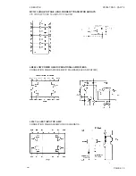
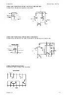
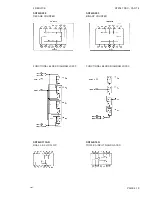
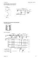
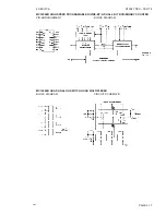
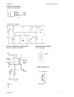
For help with trouble-shooting in the RT2047, the section 2 CIRCUIT DESCRIPTION, contains diagrams,
principal descriptions and drawings showing the location of the individual components. In the diagrams
typical values are indicated for the DC and AC voltages, just as the test points are indicated in the
diagrams.
RT2047 has a number of trimming cores and trimmers, which must not be touched, unless adjustments
like specified under section 4.5 ADJUSTMENT PROCEDURE can be made.
When measuring in the units, short-circuits must be avoided as the transistors could be destroyed.
A great help for trouble-shooting is the TEST PROGRAMMES FOR RT2047 mentioned in section 3. of
the manual: INSTRUCTIONS FOR IDENTITY AND SERVICE PROGRAMMING OF VHF RT2047.
Therefore we recommend all service personal to read sections 3,4 and 5 where the fault finding facilities
in the test programmes are located.
4.8
REPLACEMENT OF COMPONENTS
Changing of transistors, diodes, resistors, capacitors and similar components will involve the use of a
small “pencil” soldering iron of 30 to 75 Watt rating. The soldering must be performed rapidly to avoid over
heating, and the use of a tin sucker is recommended, as there is a risk that both the components and the
printed circuit will be damaged otherwise.
4.9
REPLACEMENT OF MODULES
If a fault has been located to certain module time can be saved by replacing it and repairing it on a later
occasion.
PAGE 4-6
9545
Содержание RT2047
Страница 1: ...S P RADIO A S AALBORG DENMARK TECHNICAL MANUAL FOR COMPACT VHF RT2047 D ...
Страница 2: ......
Страница 5: ...RT2047 DSC PART I CONTENTS 1 GENERAL INFORMATION 1 1 1 1 INTRODUCTION 1 1 ...
Страница 6: ......
Страница 8: ......
Страница 10: ......
Страница 24: ......
Страница 30: ...1 GENERAL INFORMATION RT2047 DSC PART II PAGE 1 6 9543 ...
Страница 32: ......
Страница 34: ......
Страница 46: ...2 CIRCUIT DESCRIPTION RT2047 DSC PART II PAGE 2 12 9543 ...
Страница 50: ...2 CIRCUIT DESCRIPTION RT2047 DSC PART II 9543 PAGE 2 16 ...
Страница 66: ...9546 ...
Страница 67: ...2 CIRCUIT DESCRIPTION RT2047 DSC PART II 9546 PAGE 2 33 32162 ...
Страница 81: ......
Страница 82: ......
Страница 84: ......
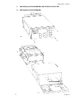
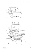
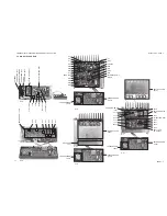
Страница 85: ...PAGE 3 1 9545 3 MECHANICAL DISASSEMBLING AND MODULE LOCATION 3 1 MECHANICAL DISASSEMBLING RT2047 DSC PART II ...
Страница 86: ...3 MECHANICAL DISASSEMBLING AND MODULE LOCATION RT2047 DSC PART II PAGE 3 2 9545 ...
Страница 88: ......
Страница 90: ......
Страница 98: ...4 SERVICE RT2047 DSC PART II PAGE 4 8 9545 ...
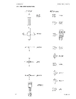
Страница 99: ...4 SERVICE RT2047 DSC PART II 4 11 PIN CONFIGURATION 9545 PAGE 4 9 ...
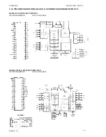
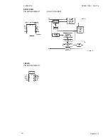
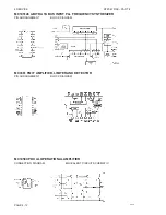
Страница 101: ...4 SERVICE RT2047 DSC PART II NMC93C56N PIN ARRANGEMENT BLOCK DIAGRAM LM393N PIN ARRANGEMENT PAGE 4 11 9545 ...
Страница 109: ...RT2047 DSC PART II CONTENTS 5 PARTS LISTS 5 1 9546 ...
Страница 110: ......
Страница 124: ......


