


4 SERVICE
RT2047 DSC - PART II
ADJUSTMENT OF TX-DRIVE LEVEL.
1.
Remove coax cable from TX-PA and solder a 50
W
resistor from TX to PA output to ground.
2.
Connect test probe to TX to PA output.
3.
Adjust coils L306 and L307 to Max deflection on the Tp meter and ensure that the levels on ch. 6
and ch. 28 are nearly the same.
4.
Adjust R341 to the correct output: about 3.8V on the Tp meter.
5.
Remove the 50
W
resistor and solder the coax cable back to the output point.
4.6.4
ADJUSTMENTS OF TX-POWER AMPLIFIER MODULE 400
ADJUSTMENT OF OUTPUT POWER.
1.
Select channel 20.
2.
Connect RF-power meter and a 50
W
/ 25 Watt load resistor to the antenna connector J801.
3.
Adjust trimming capacitors C423, C419, C413, C408, C407 to Max. deflection on the power meter.
4.
Repeat the adjustment under part 3 several times to get Max. output power.
5.
Adjust R68-6 on interface unit until the power meter shows 25 Watt. Max PA regulator Vcc = 10.5V.
6.
Set output power to 1W.
7.
Adjust R29-6 on the interface unit until the power meter shows 0.8 Watt.
4.6.5
ADJUSTMENT OF MODULATION ON INTERFACE UNIT MODULE 6/600
1.
Select channel 28.
2.
Disconnect the blue wire on the Filter Unit coming from J3-8 pin 3.
3.
Connect tone generator and AF Volmeter between the solder terminal for the disconnected blue
wire and ground (the white wire next to it).
4.
Set power output level to 1W.
5.
Connect modulation meter loosely to the RF-load resistor.
6.
Connect distortion analyzer to the modulation meter.
7.
Turn potentiometer R61 to the middle of its adjustment range.
8.
Set the tone generator to a frequency of 1000 Hz and the output level to 1 V
RMS
(nominal level 100
mV
RMS
+ 20 dB). Read the level on the AF-volmeter.
9.
Key the transmitter.
10.
Adjust R23-6 to Max. deviation:
D
F = + 5.0 kHz.
11.
Set level of tone generator to nominal level: 100 mV
RMS
.
12.
Adjust R61-6 to nominal modulation:
D
F = + 3.0 kHz.
13.
Check that the distortion is less than 5%.
4.6.6
ADJUSTMENT OF RECEIVER UNIT MODULE 100
ADJUSTMENT OF RF AND IF AMPLIFIER
1.
Select channel 28.
2.
Connect the signal generator to the antenna connector J801.
3.
Connect the test probe to pin 16 on U101.
4.
Set the signal generator frequency to 162.000 MHz and increase the level until the deflection on
the T
p
meter reaches 30% of maximum deflection.
5.
Readjust the signal generator level during the adjustment, if necessary to keep the same deflection
on the T
p
meter. You must be sure that the signal is not compressed.
6.
Adjust coils L101, L102, L103, L104, L105, L106 to maximum deflection on the T
p
meter.
7.
Select channel 6.
8.
Set signal generator to 156.300 MHz.
9.
Adjust potentiometer R16-6 (interface unit) to maximum deflection on the T
p
meter.
10.
Select channel 28.
11.
Set the signal generator frequency to 162.000 MHz.
12.
Adjust coils L101, L102, L103, L104 to maximum deflection on the T
p
meter.
PAGE 4-4
9545
Содержание RT2047
Страница 1: ...S P RADIO A S AALBORG DENMARK TECHNICAL MANUAL FOR COMPACT VHF RT2047 D ...
Страница 2: ......
Страница 5: ...RT2047 DSC PART I CONTENTS 1 GENERAL INFORMATION 1 1 1 1 INTRODUCTION 1 1 ...
Страница 6: ......
Страница 8: ......
Страница 10: ......
Страница 24: ......
Страница 30: ...1 GENERAL INFORMATION RT2047 DSC PART II PAGE 1 6 9543 ...
Страница 32: ......
Страница 34: ......
Страница 46: ...2 CIRCUIT DESCRIPTION RT2047 DSC PART II PAGE 2 12 9543 ...
Страница 50: ...2 CIRCUIT DESCRIPTION RT2047 DSC PART II 9543 PAGE 2 16 ...
Страница 66: ...9546 ...
Страница 67: ...2 CIRCUIT DESCRIPTION RT2047 DSC PART II 9546 PAGE 2 33 32162 ...
Страница 81: ......
Страница 82: ......
Страница 84: ......
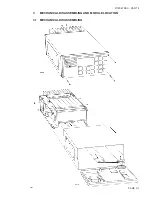
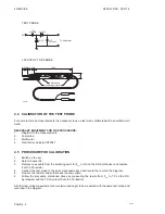
Страница 85: ...PAGE 3 1 9545 3 MECHANICAL DISASSEMBLING AND MODULE LOCATION 3 1 MECHANICAL DISASSEMBLING RT2047 DSC PART II ...
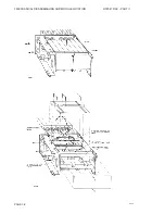
Страница 86: ...3 MECHANICAL DISASSEMBLING AND MODULE LOCATION RT2047 DSC PART II PAGE 3 2 9545 ...
Страница 88: ......
Страница 90: ......
Страница 98: ...4 SERVICE RT2047 DSC PART II PAGE 4 8 9545 ...
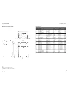
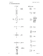
Страница 99: ...4 SERVICE RT2047 DSC PART II 4 11 PIN CONFIGURATION 9545 PAGE 4 9 ...
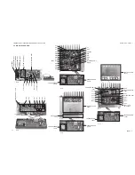
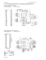
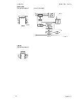
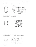
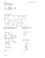
Страница 101: ...4 SERVICE RT2047 DSC PART II NMC93C56N PIN ARRANGEMENT BLOCK DIAGRAM LM393N PIN ARRANGEMENT PAGE 4 11 9545 ...
Страница 109: ...RT2047 DSC PART II CONTENTS 5 PARTS LISTS 5 1 9546 ...
Страница 110: ......
Страница 124: ......


