


2 CIRCUIT DESCRIPTION
RT2047 DSC - PART II
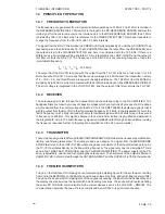
2.2
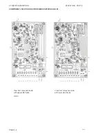
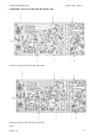
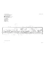
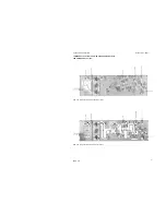
RX-SYNTHESIZER UNIT MODULE 200
The RX-synthesizer unit includes the following circuits:
2.2.1
RX-VCO AND BUFFER AMPLIFIERS
The transistor T203 is producing 8.3 V supply voltage for the RX-VCO and bias for the buffer amplifiers
consisting of the transistors T201 and T204. The RX-VCO comprises a Field Effect Transistor T202 (the
oscillator transistor), two coaxial coils L203, L204, two capacitors C212, C214, and a variable capacitance
diode D201. The frequency is mainly determined by the components L203, L204, C214, and D201. The
RX-VCO is a voltage controlled oscillator where the control voltage from the loop filter determines the
frequency by means of D201. A high control voltage to the variocap. diode D201 means a small
capacitance in the diode which means a high frequency of the VCO. In the opposite way a low control
voltage means a low VCO frequency. The RX-VCO signal is passed to two buffer amplifiers via low pass
filter C209, C206, L201. The L01 buffer transistor T201 is producing 5 mW for the 1st mixer in the receiver.
The 5 mW is taken from the tuned filter L202, R202, C207, and C208. The prescaler buffer transistor T204
is producing 0.25 mW for the 16.8 MHz mixer in the TX-Exciter-Unit. It is also producing signal for 32/33
prescaler. The signal from transistor T204 is led through a low pass filter C217, L206, and C222. The gain
in both buffers can be adjusted by the potentiometer R209.
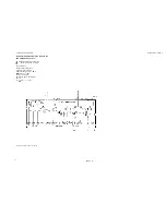
2.2.2
32/33 PRESCALER
The integrated circuit IC201 is a two modulus prescaler based on the ECL technique. From the control
logic in the programmable divider IC202 pin 14, a high or low level is led to the prescaler IC201 pin 1. A
high level at IC201 pin 1 causes the prescaler to divide by 33 and in turn a low level at pin 1 sets it up for
dividing by 32. The resistor R232 and the diode D204 work as a speed-up circuit.
2.2.3
THE PROGRAMMABLE DIVIDER
The programmable divider IC202 contains two phase detectors, a lock detector, a reference divider, an
A-counter, a N-counter, control logic, and 8 latches. Only phase detector B of the detectors is in use. When
the VHF is switched on the microcomputer will load dividing figures into the reference divider and into the
A and N-counters. The microcomputer loads only one latch at a time.
By setting up a code at the address inputs Al - A2 the microcomputer selects a latch and at the same time
a code for the dividing figure is set up at the data inputs D0 - D3. The microcomputer sends a strobe pulse
to IC202 pin 12 and the selected latch is loaded. The procedure is then repeated until all the latches are
loaded.
When the channel or the function of the VHF is changed it is only the latches for the A and N-counter that
change data. The reference frequency is 2.1 MHz and it is constant. Therefore it is not necessary to
change the dividing figure every time.
In the beginning of a counting period the prescaler IC201 starts dividing by 33 and the A and N-counters
count down. First the A-counter reaches zero and stops counting and the control logic shifts the prescaler
to divide by 32. Then the N-counter reaches zero and sends a pulse to the phase detector B, and the
control logic shifts the prescaler to divide by 33. The control logic also reloads the A and N-counters with
data from their latches and the whole procedure starts from the beginning.
The pulse frequency from the reference divider is 12.5 KHz. If the RX-VCO frequency is correct the pulse
frequency of the N-counter is also 12.5 KHz and in phase with the pulse from the reference divider. The
phase detector B compares the phase of the two pulses. If they are not in phase the detector sends
correction pulses to the phase-detector-pump for correcting the frequency/phase of the RX-VCO.
However, the synthesizer circuit is born with a small phase error, therefore the phase detector is sending
small correction pulses to transistor T210 with a frequency of 12.5 KHz.
PAGE 2-4
9543
Содержание RT2047
Страница 1: ...S P RADIO A S AALBORG DENMARK TECHNICAL MANUAL FOR COMPACT VHF RT2047 D ...
Страница 2: ......
Страница 5: ...RT2047 DSC PART I CONTENTS 1 GENERAL INFORMATION 1 1 1 1 INTRODUCTION 1 1 ...
Страница 6: ......
Страница 8: ......
Страница 10: ......
Страница 24: ......
Страница 30: ...1 GENERAL INFORMATION RT2047 DSC PART II PAGE 1 6 9543 ...
Страница 32: ......
Страница 34: ......
Страница 46: ...2 CIRCUIT DESCRIPTION RT2047 DSC PART II PAGE 2 12 9543 ...
Страница 50: ...2 CIRCUIT DESCRIPTION RT2047 DSC PART II 9543 PAGE 2 16 ...
Страница 66: ...9546 ...
Страница 67: ...2 CIRCUIT DESCRIPTION RT2047 DSC PART II 9546 PAGE 2 33 32162 ...
Страница 81: ......
Страница 82: ......
Страница 84: ......
Страница 85: ...PAGE 3 1 9545 3 MECHANICAL DISASSEMBLING AND MODULE LOCATION 3 1 MECHANICAL DISASSEMBLING RT2047 DSC PART II ...
Страница 86: ...3 MECHANICAL DISASSEMBLING AND MODULE LOCATION RT2047 DSC PART II PAGE 3 2 9545 ...
Страница 88: ......
Страница 90: ......
Страница 98: ...4 SERVICE RT2047 DSC PART II PAGE 4 8 9545 ...
Страница 99: ...4 SERVICE RT2047 DSC PART II 4 11 PIN CONFIGURATION 9545 PAGE 4 9 ...
Страница 101: ...4 SERVICE RT2047 DSC PART II NMC93C56N PIN ARRANGEMENT BLOCK DIAGRAM LM393N PIN ARRANGEMENT PAGE 4 11 9545 ...
Страница 109: ...RT2047 DSC PART II CONTENTS 5 PARTS LISTS 5 1 9546 ...
Страница 110: ......
Страница 124: ......


